Getting started with STM MCUs: STM32G070 Nucleo
STM32G070 Nucleo board (NUCLEO-G070RB) and X-NUCLEO-GFX01M1 display expansion board.
The following article explains all necessary steps to create an Embedded Wizard UI application suitable for the STM32G070 Nucleo board. Please follow these instructions carefully and step by step in order to ensure that you will get everything up and running on your target. In case you are not familiar with Embedded Wizard, please read first the Quick Tour tutorial to understand the principles of Embedded Wizard and the GUI development workflow.
Introduction: External display controller and partial display updates
The STM32G070 Nucleo board combines the STM32 micro-controller (MCU) with a 320x240 display, driven by an external display controller connected via SPI. The display controller contains its own display memory, so that the entire framebuffer can be located inside the display controller and only a small scratch-pad buffer is needed inside the micro-controller (MCU). For this purpose, Embedded Wizard supports a partial display update, that makes it possible to update the display in sequential small areas. This makes it possible to operate with a scratch-pad buffer of a few kilobytes instead of a full-screen framebuffer within the memory space of the MCU.
Please note: The partial display update is intended to be used for extremely memory-constrained systems. Due to the fact that the display update is done in subsequent updates of small areas, moving graphical objects can cause some tearing effects. The UI design should consider this aspect.
Prerequisites
Although you can combine the STM32G070 Nucleo board with many different display controllers or your own hardware, we highly recommend to start first with the following hardware components in order to ensure that you get the entire software up and running. As soon as you have your first UI application working on the recommended environment, you can start porting to your desired display controller.
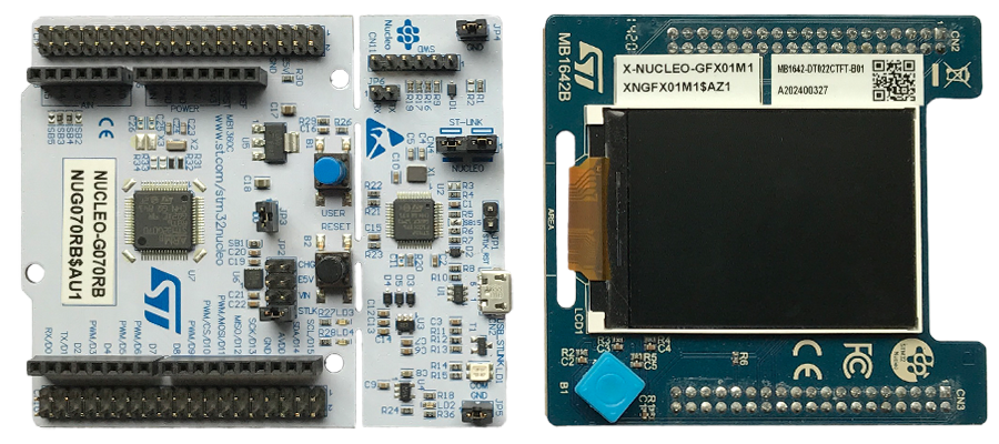
STM32G070 Nucleo board (NUCLEO-G070RB) and X-NUCLEO-GFX01M1 display expansion board.
For a smooth bring-up session, you need the following hardware components:
★STM32G070 Nucleo board from STMicroelectronics (NUCLEO-G070RB)
★Display expansion board for STM32 NUCLEO from STMicroelectronics (X-NUCLEO-GFX01M1)
★USB cable to connect the board with your PC
Make sure that you have got the following software packages:
★Embedded Wizard Studio Free or Embedded Wizard Studio Pro
★Embedded Wizard STM32 Platform Package
★Embedded Wizard Build Environment for STM32G070 Nucleo
IMPORTANT
If you want to evaluate Embedded Wizard Studio and the STM32 Platform Package in combination with the STM32G070 Nucleo board, please contact us in order to download the above software packages.
All customers who licensed Embedded Wizard for the STM32G0 family can visit our download center to get the above software packages.
Installing Tools and Software
★Step 1: Install the latest version of Embedded Wizard Studio.
★Step 2: Install the Embedded Wizard STM32 Platform Package.
★Step 3: Download the STM32CubeProgrammer and install it. Test the connection from PC to Nucleo board and the proper installation of the USB drivers: Connect the Nucleo board with your PC via USB (make sure to use the ST-LINK USB connector) and start the previously installed STM32CubeProgrammer. Select the green button and verify that the connection could be established successfully. Finally, close the STM32CubeProgrammer utility.
★Step 4: Unpack the provided Embedded Wizard Build Environment for STM32G070 Nucleo to your local file system (e.g. C:\STM32\STM32G070-Nucleo).
★Step 5: Take a text editor and open the file FlashDownload.cfg that you will find in the subdirectory \Application\FlashDownload of the Build Environment. At the beginning of the file, the following environment variable has to be set to the installation path of the STM32CubeProgrammer utility:
•Stm32CubeProgrammerPath - Absolute path of your installed STM32CubeProgrammer utility (Step 3).
Exploring the Build Environment
The provided Embedded Wizard Build Environment for STM32G070 Nucleo contains everything you need to create, compile, link and flash an Embedded Wizard UI application for the STM32G070 target. After unpacking, you will find the following subdirectories and files:
•StartGccBuildEnvironment.bat - This script file is provided to start a windows command line to build your GUI applications for the target.
•\Application - This folder contains ready-to-use projects to compile and link an Embedded Wizard generated UI application. They are used for all provided examples and they can be used to build your own UI applications.
•\FlashDownload - This folder contains a script to load the created binaries into the flash of your target by using the STM32CubeProgrammer tool. Don't forget to set the path of your installed STM32CubeProgrammer utility within the file FlashDownload.cfg.
•\GeneratedCode - This folder is used to receive the generated code from an Embedded Wizard UI project. All template projects are building the UI application out of this folder. You can create your own UI project and generate the code into the subdirectory \GeneratedCode without the need to adapt the project.
•\Project - This folder contains the prepared projects for GCC (make) and STM32CubeIDE.
•\Source - This folder contains the files main.c and ewmain.c. There you will find the initialization of the system and the main loop to drive an Embedded Wizard GUI application. The file ewconfig.h contains general configuration settings for the target system, like memory ranges and display parameter and configuration settings for the Embedded Wizard Graphics Engine and Runtime Environment. Additionally, this folder contains a configuration file for FreeRTOS and the device driver C/H files used for the DeviceIntegration example.
•\Examples - This folder contains a set of demo applications. Each example is stored in a separate folder containing the entire Embedded Wizard UI project. Every project contains the necessary profile settings for the STM32G070 target. The following samples are provided:
•\HelloWorld - A very simple project that is useful as starting point and to verify that the entire toolchain, your installation and your board is properly working.
•\ScreenOrientation - This demo shows, that the orientation of the UI application is independent from the physical orientation of the display.
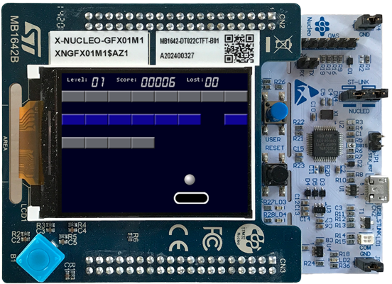
•\BrickGame - The sample application BrickGame implements a classic "paddle and ball" game. In the game, a couple of brick rows are arranged in the upper part of the screen. A ball travels across the screen, bouncing off the top and side walls of the screen. When a brick is hit, the ball bounces away and the brick is destroyed. The player has a movable paddle to bounce the ball upward, keeping it in play.
•\PlatformPackage - This folder contains the necessary source codes of the STM32 Platform Package: The Graphics Engines for the RGB565 color format and the Runtime Environment (in the subdirectory \RTE).
•\TargetSpecific - This folder contains all configuration files and platform specific source codes. The different ew_bsp_xxx files implement the bridge between the Embedded Wizard UI application and the underlying board support package (STM32 hardware drivers) in order to access the display, the serial interface and the clock.
•\ThirdParty - This folder contains third-party source codes and tools:
•\gcc-arm-none-eabi - This folder contains a subset of the GCC ARM embedded toolchain to compile the examples.
•\Make - This folder contains a make tool to build the entire GUI application via command line.
•\STM32Cube_FW_G0 - This folder contains the necessary subset of the STM32CubeG0 embedded software for STM32G0 series used for the Embedded Wizard UI applications (HAL, BSP, drivers, FreeRTOS).
Creating the UI Examples
For the first bring up of your system, we recommend to use the example 'HelloWorld':
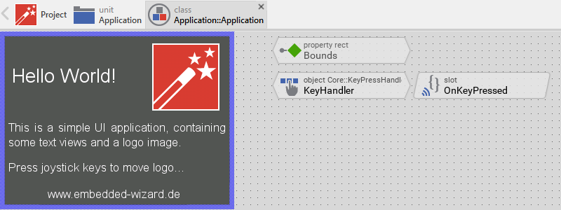
Example 'HelloWorld' within Embedded Wizard Studio.
The following steps are necessary to generate the source code of this sample application:
★Navigate to the directory \Examples\HelloWorld.
★Open the project file HelloWorld.ewp with your previously installed Embedded Wizard Studio. The entire project is well documented inline. You can run the UI application within the Prototyper by pressing Ctrl+F5.
★To start the code generator, select the menu items - or simply press F8. Embedded Wizard Studio generates now the sources files of the example project into the directory \Application\GeneratedCode.
Compiling, Linking and Flashing
The following steps are necessary to build and flash the Embedded Wizard UI sample application using the GCC ARM embedded toolchain:
★Navigate to the top level of the Build Environment.
★Open StartGccBuildEnvironment.bat - as a result, a windows command line window should open. In case there are error messages, please edit the file and double-check the path settings.
★Now start compiling, linking and flashing:
make make install
If everything works as expected, the application should be built and flashed to the STM32G070 target.
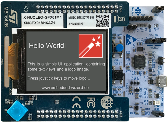
Example 'HelloWorld' running on STM32G070 Nucleo board.
All other examples can be created in the same way: Just open the desired example with Embedded Wizard Studio, generate code and rebuild the whole application using simply:
make install
Creating your own UI Applications
In order to create your own UI project suitable for the STM32G070 target, you can create a new project and select the STM32G070 Nucleo project template:
As a result you get a new Embedded Wizard project, that contains the necessary Profile attributes suitable for the STM32G070 Nucleo board:
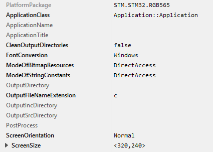
The following profile settings are important for your target:
★The attribute PlatformPackage should refer to an installed STM32 Platform Package. Please note, that for STM32G070 only the color formats RGB565 can be used.
★The attribute ScreenSize should correspond to the display size of the STM32G070 Nucleo board.
★The attributes ModeOfBitmapResources and ModeOfStringConstants should be set to DirectAccess. This ensures that the resources are taken directly from flash memory.
★The attribute OutputDirectory should refer to the \Application\GeneratedCode directory within your Build Environment. By using this template, it will be very easy to build the UI project for your target.
★The attribute CleanOutputDirectories should be set to true to ensure that unused source code within the output directory \Application\GeneratedCode will be deleted.
★The attribute PostProcess should refer to \Application\Project\STM32CubeIDE\STM32G070-Nucleo\STM32CubeIDE_ew_post_process.cmd if you are working with STM32CubeIDE. In case of the GCC ARM embedded toolchain leave it blank
Now you can use the template project in the same manner as it was used for the provided examples to compile, link and flash the binary.
After generating code, please follow these steps, in order to build your own UI application:
★Start the batch file 'StartGccBuildEnvironment.bat'. Again, a windows command line window should open.
★Start compiling, linking and flashing:
make install
Most of the project settings are taken directly out of the generated code, like the color format or the screen orientation. Only a few additional settings can be configured directly within the Makefile, like the usage of an external flash memory or the usage of the FreeRTOS operating system.
Console output
In order to receive error messages or to display simple debug or trace messages from your Embedded Wizard UI application, a serial terminal like 'Putty' or 'TeraTerm' should be used.
★As soon as you connect your STM32G070 target with the PC via USB, a STMicroelectronics STLink Virtual COM Port (COMx) appears within your system device list. Open the device manager to get the number of the installed COM port.
★Now you can open your terminal application and connect it via COMx with the following settings: 115200-8-N-1
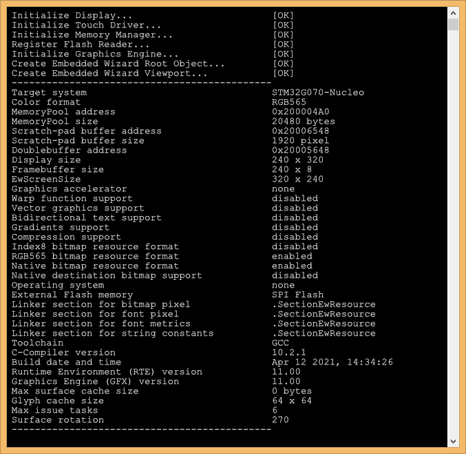
This terminal connection can be used for all trace statements from your Embedded Wizard UI applications or for all debug messages from your C code.
Using STM32CubeIDE
If you want to use the STM32CubeIDE toolchain instead of the GCC ARM embedded toolchain, please follow these instructions:
The subdirectory \Application\Project\STM32CubeIDE contains a template project that is commonly used for all provided Embedded Wizard examples. All Embedded Wizard examples will store the generated code within the common \Application\GeneratedCode folder.
The following steps are needed to establish this automatic project import:
★Open the desired Embedded Wizard example project.
★Select the Profile and set the attribute PostProcess to the file ..\..\Application\Project\STM32CubeIDE\STM32G070-Nucleo\STM32CubeIDE_ew_post_process.cmd.
After the Embedded Wizard code generation the installed post process will adapt the .cproject XML file. All necessary libraries and include paths (depending on the color format and screen rotation) will be set automatically.
The given STM32CubeIDE example under \Application\STM32CubeIDE contains a workspace which has all adaptions for an Embedded Wizard project. For using this within STM32CubeIDE do following steps:
★Open STM32CubeIDE and select the directory \Application\Project\STM32CubeIDE as workspace directory.
★To import the C project, select the menu item and choose General - Existing Projects into Workspace and press Next.
★Choose Select root directory - Browse and select the directory \Application\Project\STM32CubeIDE\STM32G070-Nucleo.
★Press Finish.
★To compile the project press the Build button (hammer symbol) within the toolbar.
★Choose the menu item to flash and start the application on the target or choose to flash and debug the application.
If the screen orientation was changed, please do a clean in STM32CubeIDE.
Custom specific hardware
In order to bring-up an Embedded Wizard generated UI application on your STM32 custom hardware, you can use the provided Embedded Wizard Build Environment for STM32G070 Nucleo as a template. The subdirectory \TargetSpecific contains all configuration files and platform specific source codes. Assuming that your custom hardware is similar to the STM32G070 Nucleo board, the following adaptations or configurations are typically necessary:
★System clock (ew_bsp_system.c) - The first and the important step is to configure the system and peripheral clock. Depending on your hardware you can use the internal or external clock as source. Please take care that your peripherals are connected to the selected clock source and configured correctly. The Embedded Wizard UI application runs independent from the chosen system frequency, however, with a slow system clock, all components need more time for their tasks (e.g. display refresh).
★USART (ew_bsp_console.c) - Typically, the USART configuration just requires a new pinout according your hardware layout. The usage of the serial connection is highly recommended in order to get status and debug messages during runtime.
★Display (ew_bsp_display.c) - Adapt the file \TargetSpecific\ew_bsp_display.c to access the desired display driver (external display controller with own graphics memory).
★Touch (ew_bsp_touch.c) - If your application requires touch support, you can integrate a given touch driver provided by the touch controller manufacturer or write your own. As a result the current touch position should be returned.
As soon as these steps are done, you can create your own GUI application or use one of the provided examples. If the size of your display is different compared to the display of the STM32G070 Nucleo board (320x240 pixel), please adapt the attribute ScreenSize of the UI project and the size of the framebuffer within the file ewconfig.h accordingly.
Release notes
The following section contains the version history of the Build Environment (including Graphics Engine and Runtime Environment) for STM32G070 Nucleo. These release notes describe only the platform specific aspects - for all general improvements and enhancements please see the Embedded Wizard release notes.
Version 11.00
★Initial support of STM32G070 Nucleo board with access of non-direct addressable SPI flash.
★Flash download: Flashing the binary to the target is now controlled by one dedicated script that is used from the makefile and the other toolchains. The script is located in the subdirectory \Application\FlashDownload. The settings can be changed within the file FlashDownload.cfg.
★Linker section definitions: The linker section definitions for constant data can now be done directly within the file ewconfig.h. The set of defines have been enhanced to control the location of all types of constant data. The following defines are supported: EW_USE_EXTERNAL_FLASH, EW_BITMAP_PIXEL_SECTION_NAME, EW_FONT_PIXEL_SECTION_NAME, EW_FONT_DATA_SECTION_NAME, EW_CONST_STRING_SECTION_NAME.
★Touch configuration and calibration: The file ewconfig.h contains now a set of defines to print and calibrate the touch events from the touch device.
★Code size reduction: A set of new macros wtihin the file ewconfig.h are introduced to reduce the code size of the binary application: EW_DONT_USE_GRADIENTS, EW_DONT_USE_COMPRESSION, EW_DONT_USE_NATIVE_SURFACES, EW_DONT_USE_NATIVE_SURFACES_AS_DESTINATION.
★Using STM32CubeG0 Firmware Package V1.4.0.
★Using GCC ARM Embedded Toolchain 10-2020-q4-major.
Version 11.00.01
★Downgrade of GCC ARM embedded toolchain from 10-2020-q4-major back to 9-2020-q2-update used for building the binary. In some cases the dependency files that are created during compilation contain erroneous path entries. As a result the next make fails with 'no rule to make target C\:\STM32'.
Version 11.00.02
★Changed to STM32CubeProgrammer V2.10.0.
★Prepared FlashDownload.cmd file to work with STM32CubeProgrammer V2.10.0.