Using Views: Path Data
The Mosaic framework provides the views Filled Path and Stroked Path intended to display vector graphic shapes (polygons, curves, diagrams, etc.) from provided path data. Depending on the respective view, the shape appears filled (Filled Path view) or as lines drawn along its path edges (Stroked Path view). In order to display a shape, the views require path the information describing the shape precisely.
In its simplest form, a path is composed of line segments, Bézier curves and elliptical arcs. The path can be opened (e.g. a curve within a diagram) or it can be closed (e.g. to describe a circle). In more sophisticated application cases you can compose several sub-paths to one complex path. For example, with two sub-paths, every describing a circle, you can create easily a ring. To construct and store the path you use the so-called Path Data object.
The following sections are intended to provide you an introduction and useful tips of how to deal with the Path Data object. For the complete reference please see the documentation of the Graphics::Path class. Please note, with Path Data object you only describe the desired shape. Attributes like colors, line thickness, winding rules, line join style or line caps are determined by properties of the respective view used to fill or stroke the path.
SEE ALSO
Using the Filled Path view to fill a polygon described by a vector graphic path
Using the Stroked Path view to display the outline of a vector graphic path
Please note, the Mosaic framework provides also a descendant of the generic Path Data object, the so-called Arc Path Data object. This object is ideal when you intend to create path data describing arcs, pie segments, circle segments or even ring segments. Unlike the generic Path Data object, with Arc Path Data you don't need to implement code to describe the path. You simply configure the parameters for the arc by using properties of the Arc Path data object. On the other hand, with Arc Path Data you are limited to deal with elliptical shapes only.
Add new Path Data object
To add a new Path Data object just at the design time of a GUI component do following:
★First ensure that the Templates window is visible.
★In Templates window switch to the folder Resources.
★In the folder locate the template Path Data.
★Drag & Drop the template into the Composer window:
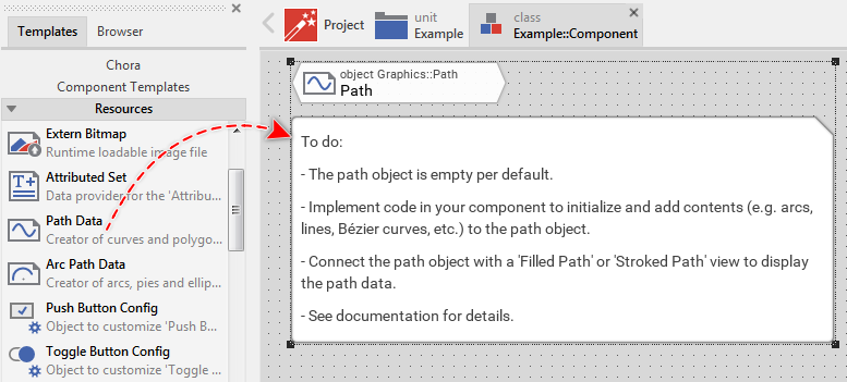
★Eventually name the new added Path Data object.
The new added Path Data objects appear accompanied by an annotation providing helpful tips how to proceed. If undesired, you can select and delete the annotation.
Connect the Path Data object to a view
The Path Data object serves as data container where you store the description of a shape. In order to display this shape on the screen you have to connect the Path Data object to one of the both views Filled Path or Stroked Path. Accordingly, the view will display a filled shape (Filled Path view) or it will draw lines along the path edges (Stroked Path view).
To connect a Path Data object to a view you have to assign this object to the property Path of the affected Filled Path or Stroked Path view. With the Inspector Assistant you can conveniently select the right object when you edit the initialization expression for the property Path. For example:
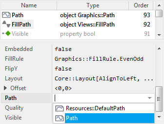
As soon as you have connected the both, the information provided in the Path Data object appears within the view. If desired, you can assign the same Path Data object to several views. If during the runtime of the application, the content of the Path Data object changes, all associated views are updated automatically.
CAUTION
If after assigning the Path Data object to a view, the view displays the shape clipped, you will need to resize the view and adjust its property Offset. With the property Offset you determine the position within the view where to map the origin of the path own coordinate system.
Specify the maximum number of sub-paths
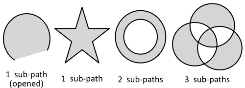
Per default, new Path Data objects are able to store only one sub-path. This is sufficient for the most typical application cases. With one sub-path you can describe a circle, an arc, a sequence of Bézier curves or even a complex polygon. However, if you want to display a ring, then you need two sub-paths. With the first sub-path you define the outer circle and with the second sub-path the inner circle of such ring. The following figure demonstrates diverse shapes composed of one or more sub-paths:
To configure how many sub-paths the Path Data object should be able to manage you call its method SetMaxNoOfSubPaths() and pass in its unique argument the number of sub-paths you intend to maximally store in this path. For example, to prepare the Path Data object to be able to store up to 4 sub-paths, execute following code just before you start to fill the Path Data object with contents:
Path.SetMaxNoOfSubPaths( 4 );
The actual capacity of a Path Data object can be queried by using the method GetMaxNoOfSubPaths(). For example, with the following code you increase the capacity of the Path Data object to be able to manage 3 sub-paths more:
Path.SetMaxNoOfSubPaths( GetMaxNoOfSubPaths() + 3 );
With the invocation of the method SetMaxNoOfSubPaths() you just prepare the Path Data object to be able to manage up to the specified number of sub-paths. Whether you really provide path contents for every sub-path or you don't it is up to you. Sub-paths which are not initialized, remain empty as if they were not existing.
TIP
When changing the capacity of a Path Data object all old contents existing till now in the object are discarded. In other words, after this operation the Path Data object is empty and ready to be filled with new path information. Therefore it is optimal to call SetMaxNoOfSubPaths() just at the initialization time of the GUI component or more simply shortly before the Path Data object is loaded with contents for the first time.
Initialize a sub-path
Before you can start to construct a path from line segments, Bézier curves or arcs, you have to inform the Path Data object to reserve sufficient amount of memory for the intended information. Internally, the path is stored as a list of connected straight line segments, so-called edges. Accordingly, you will need to estimate the number of edges in the shape you intend to construct.
For example, if you plan to construct a rectangular shape you will need at least 4 edges to describe it. If you plan to construct a 5 angular star, you need 10 edges. If you plan to construct an arc or circle, the number of edges depends on how finely resolved should the arc appear. The more edges used to describe the arc the more precise the resulting image. The following figure demonstrates diverse shapes how they are composed of edges:

To instruct the Path Data object to reserve memory for the intended (maximum) number of edges you call its method InitSubPath(). The method expects in its first argument a number identifying the affected sub-path. Accordingly, if you have configured the path to use more than 1 sub-path, you have to specify the desired number of edges for every sub-path individually. Assuming you want to construct a ring with its outer circle composed of up to 100 edges and its inner circle composed of up to 70 edges, then following code will instruct the Path Data object to reserve the correct amount of memory for the path information:
// First ensure the Path Data object can manage up to 2 sub-paths Path.SetMaxNoOfSubPaths( 2 ); // Initialize (reserve memory) for the first sub-path (the outer circle) Path.InitSubPath( 0, 100 ); // Initialize (reserve memory) for the second sub-path (the inner circle) Path.InitSubPath( 1, 70 );
With the invocation of the method InitSubPath() you just prepare the Path Data object to be able to store in the particular sub-path up to the specified number of edges. Whether you really provide path contents for all edges or you don't it is up to you. After being initialized, all edges of the sub-path are empty and you can start to add information to the path as described in the following section. In other words, InitSubPath() clears the affected sub-path.
If you want to query how many edges are actually occupied within a sub-path or how many edges are still free and available to store further path information, you can use the methods GetNoOfEdges() and GetNoOfFreeEdges().
Store data in a sub-path
Once you have initialized a sub-path you can start to fill it with path information to describe the desired shape. For this purpose following methods are available. By combining the methods you can easily construct complex shapes composed of several line segments, arcs and Bézier curves:
Method |
Description |
|---|---|
Sets the start position for the sub-path. Beginning with the specified position, the path can be filled with curve data by using the methods AddLine(), AddArc(), AddBezier2() and AddBezier3(). Calling this method for a sub-path containing already edge coordinates will delete the existing sub-path contents. |
|
Appends to the sub-path a new straight line segment with the specified end position. The start position, in turn, results from the end position of the last edge stored actually in the sub-path. If the sub-path is empty, the start position can be determined by using the method Begin() otherwise it is 0,0. The line is always composed of a single edge. |
|
Appends to the actual content of the sub-path a new quadratic Bézier curve. With the method arguments you specify the Bézier curve control point, the end position of the curve and the number of edges to compose it. The start position, in turn, results from the end position of the last edge stored actually in the sub-path. If the sub-path is empty, the start position can be determined by using the method Begin() otherwise it is 0,0. |
|
Appends to the actual content of the sub-path a new cubic Bézier curve. With the method arguments you specify the both Bézier curve control points, the end position of the curve and the number of edges to compose it. The start position, in turn, results from the end position of the last edge stored actually in the sub-path. If the sub-path is empty, the start position can be determined by using the method Begin() otherwise it is 0,0. |
|
Adds to the sub-path a new elliptical arc. With the method arguments you specify the ellipse center, its radiuses in vertical and horizontal direction, the angles for the start and end positions and the number of edges the arc should be composed of. If there are already contents stored in the sub-path, the end position of the last existing edge and the start position of the new arc are connected by an additional straight line segment. |
|
Appends to the sub-path a copy of path information stored in another sub-path. In this manner contents from different paths can be combined together without the necessity to re-calculate them again. With the method arguments you identify the desired source sub-path and the range of its edges to copy. |
|
Marks the affected sub-path as closed. The method verifies whether the first and the last position of the sub-path are equal and if this is not the case, adds an additional straight line segment to the sub-path in order to connect them together. Once the sub-path is closed, no additional path information can be added to it unless it is initialized again or cleared by using the method Begin(). |
All methods have in common the first argument where you pass a number identifying the affected sub-path. Accordingly, if you have configured the path to use more than 1 sub-path, you have to provide path information for every sub-path individually. For example, with the following code you create a ring composed of two circles, means two sub-paths:
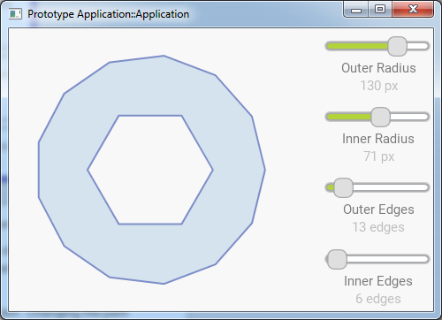
// Prepare the Path Data object to be able to store 2 sub-path. Path.SetMaxNoOfSubPaths( 2 ); Path.InitSubPath( 0, 100 ); Path.InitSubPath( 1, 70 ); // The first sub-path describes the outer circle of the ring with 150 px radius. Path.AddArc( 0, 0.0, 0.0, 150.0, 150.0, 0.0, 360.0, 100 ); // The second sub-path describes the inner circle of the ring with 110 px radius. // Note, the winding direction of the inner circle is reversed. Path.AddArc( 1, 0.0, 0.0, 110.0, 110.0, 360.0, 0.0, 70 ); // To avoid eventually visible gaps between the end and the start position of an // arc close the sub-paths. Path.Close( 0 ); Path.Close( 1 );
The following example project demonstrates the function of the above code. When you open the project in Embedded Wizard you see a GUI component containing 4 slider. Two of them are intended to change the outer and inner radius of the ring. With the other two sliders you control of how many edges the circles are composed:
Please note, the example presents eventually features available as of version 9.00
Other typical application case is to use the Path Data object as container of data describing a chart or line graph. You achieve this by simply adding to the Path Data object straight line segments - one segment for every graph value. Lets assume, there is data source in your application providing some measured values. By using this data source you can populate through the values and fill the Path Data object with line segments. The following code demonstrates the idea:
var int32 inx; // How many values are available in the data source and how width should be // the graph in pixel? var int32 noOfValues = ... var int32 graphWidth = ... // How large is the step between two values? var float stepX = float( graphWidth ) / float( noOfValues - 1 ); // Prepare the Path Data object to be able to store sufficient edges for // all data values Path.InitSubPath( 0, noOfValues ); // Get the first available value from the data source var float data = ... // The first value determines the position where the path should start. // Horizontally we begin with the left edge of the view (X=0). Path.Begin( 0, 0.0, data ); // Now iterate through the remaining values and add line segments for every // value for ( inx = 1; inx < noOfValues; inx = inx + 1 ) { // Get the next available value with the number 'inx' data = ... // ... and append the line segment Path.AddLine( 0, stepX * float( inx ), data ); }
The following example project demonstrates the function of the above code. When you open the project in Embedded Wizard you see a GUI component containing a push button. Every time you click on this button, the Path Data object is filled with new random values:
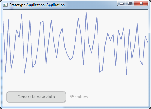
Please note, the example presents eventually features available as of version 9.00
Apply 2D transformations during the path creation
When you construct a shape from line segments, arcs or Bézier curves, all specified coordinates as well as any size parameters are per default interpreted as being expressed in pixel. For example, when you add to a path a circle with the given radius of 100.0, the circle will appear on the screen with 200 pixel diameter.
The relation between the originally provided coordinates and the resulting size of the shape as well as its orientation are controlled by the coefficients of a path own transformation matrix. With the following methods you can modify this matrix and accordingly apply the desired transformation:
Method |
Description |
|---|---|
Applies the given angle to the transformation matrix used by the affected Path Data object. This corresponds to the rotation of the path coordinate system around its origin position. |
|
Applies the given factors to the transformation matrix used by the affected Path Data object. This corresponds to the scaling of the path coordinate system by the given values in the X- and Y-direction. |
|
Applies the given displacement to the transformation matrix used by the affected Path Data object. This corresponds to the translation of the origin of the path coordinate system in the X- and Y-direction. |
|
Replaces the transformation matrix used by the affected Path Data object with the identity matrix. After this operation, the identity matrix does not describe any 2D transformations. |
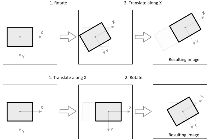
Mathematically, the matrix describes a transformation to apply on a coordinate system of the path. Scaling along X-axis stretches the coordinate system accordingly. Rotating rotates the coordinate system. With every invocation of the above described methods, a new transformation is applied to the current version of the coordinate system resulting in a new version of it. Thus you should consider all the executed transformations as cumulative and not individual. Being such it is essential in which order you perform them.
Imagine, you intend to combine the translation along the X-axis with the rotation. You have thus two possibilities: you can rotate first and then translate, or you translate first and then rotate. Depending on this order, you will get completely different results:
The modification of the transformation matrix affects only contents added subsequently to the path. Edge coordinates already stored in the path remain unchanged. Since the matrix is cumulative, calling several of the above methods in succession results in a composite transformation. For example, if you want a shape to be scaled and rotated, implement following code:
// Prepare the Path Data object Path.InitSubPath( 0, 100 ); // Because transformation matrix is cumulative, reset the matrix first. Path.InitMatrix(); // Apply the 50% scale transformation Path.Scale( 0.5, 0.5 ); // Apply the 45° degree rotation transformation Path.Rotate( 45.0 ); // Finally, add contents to the path. All coordinates specified here are // subjected to the previously specified 2D transformation. Accordingly, // the Bézier curve will appear shrunken and rotated. Path.AddBezier2( 0, ... );
The following example project demonstrates the function of the above code. When you open the project in Embedded Wizard you see a GUI component containing 3 sliders. With two of them you change the scaling factor of the displayed shape. The third slider controls the rotation of the shape. The additional radio buttons allow you to switch the order in which the scale/rotate transformations are applied:
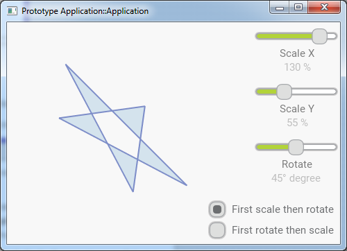
Please note, the example presents eventually features available as of version 9.00
The possibility to apply 2D transformations can be combined very well with the above described method AddCopy(). The idea: you prepare first a path containing the shape with its original coordinates. Then you use the method AddCopy() to create a copy of this prepared path information. During this copy operation you can apply any desired transformations without needing to recalculate the original path again and again. The following code uses this approach to create a complex path composed of 3 nested ellipses. All ellipses are equal except their orientation. Accordingly, it is sufficient to calculate only one ellipse and then duplicate it by applying the adequate rotation transformation:
// Prepare the Path Data object to be able to store 3 sub-path. Path.SetMaxNoOfSubPaths( 3 ); Path.InitSubPath( 0, 100 ); Path.InitSubPath( 1, 100 ); Path.InitSubPath( 2, 100 ); // In the first sub-path construct the ellipse Path.AddArc( 0, 0.0, 0.0, 300.0, 150.0, 0.0, 360.0, 100 ); Path.Close( 0 ); // Prepare the transformation to rotate coordinates by 120 degree Path.Rotate( 120.0 ) // Now copy all 100 edges from the previously prepared sub-path #0 // to a new sub-path #1. During this operation the copied coordinates // are transformed by using the previously specified rotation 120 degree. Path.AddCopy( 1, Path, 0, 0, 100 ); // Now copy all 100 edges from the sub-path #1 to a new sub-path #2. // With this operation the coordinates are rotated again by 120 degree. Path.AddCopy( 2, Path, 1, 0, 100 );
The following example project demonstrates the function of the above code. When you open the project in Embedded Wizard you see a GUI component containing one slider. With this slider you determine the number of copies to create from the original ellipse:
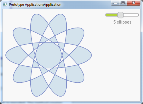
Please note, the example presents eventually features available as of version 9.00
Evaluate and modify the coordinates stored in the Path Data object
In the sections above you learned that internally the Path Data object stores the path information as a list of straight line edges. The edges, in turn, are connected by nodes which retain the corresponding coordinates. By using following methods you can easily query and modify the nodes and accordingly the position of every edge existing already in the path:
Method |
Description |
|---|---|
Returns how many edges are actually stored within a given sub-path. Accordingly, the sub-path consists of GetNoOfEdges() + 1 nodes. The nodes are numbered consecutively starting with the index 0. |
|
Returns the position of the node with a given index. This is the start position of the edge with the corresponding number and the end position of the preceding edge. |
|
Changes the position of the node with a given index. This affects the start position of the edge with the corresponding number as well as the end position of the preceding edge. |
|
Removes from a sub-path the specified number of leading nodes. This results in the path contents being shifted and the corresponding number of leading edges being discarded. After this operation new edges can be appended at the end of the sub-path, e.g. by using the method AddLine(). This technique is optimal to manage scrolling graphs, which are continuously enhanced with new data while discarding old data. |
|
Returns true if the given sub-path has been closed by calling the method Close(). Once closed, no new path edges can be added to the sub-path unless it is initialized again. The position of the nodes within the path, however, can be modified. |
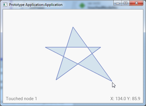
The following code example demonstrates how after being constructed you modify the coordinates stored within a path. Please node, in this example the shape is closed. Modifying its first node (means the start position of the first edge) affects implicitly the end position of the last edge:
// Prepare the Path Data object to be able to store a rectangular shape // with 4 edges Path.InitSubPath( 0, 4 ); // Construct the rectangle with 100x100 pixel size centered around // the origin of the path coordinate system. Path.Begin( 0, -50.0, -50.0 ); Path.AddLine( 0, 50.0, -50.0 ); Path.AddLine( 0, 50.0, 50.0 ); Path.AddLine( 0, -50.0, 50.0 ); Path.Close( 0 ); [...] // Later move the first node by the distance of X=10, Y=20 pixel. This // affects the start position of the first edge (#0). Since the shape is // closed, the modification also affects the end position of the last // edge (#3). Path.SetNode( 0, 0, Path.GetNodeX( 0, 0 ) + 10.0, Path.GetNodeY( 0, 0 ) + 20.0 );
The following example project demonstrates the above explained application case. When you open the project in Embedded Wizard you see a GUI component showing a simple star. In the running Prototyper you can touch and drag the corners of the star (the nodes of the path) deforming it conveniently in this manner:
Please note, the example presents eventually features available as of version 9.00
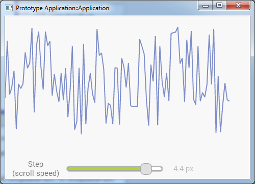
Other typical application case where you need to modify the information stored already in a Path Data object is a scrolling graph. Such graphs are continuously enhanced with new data while discarding old data. Let's assume you are developing a device intended to measure continuously some environment values and you want the values to be displayed as a curve. For this purpose, while new measured values arrive, you scroll the content of the Path Data object, discard few of its leading old values and append the new values to it. You achieve this by using the method ShiftNodes():
// How many new values are available? var int32 noOfNewValues = ... // How many additional space is required in the path to store the new values? var int32 noOfNodesToShift = noOfNewValues - Path.GetNoOfFreeEdges( 0 ); // If there is not enough space in the Path Data object, discard few of its old // edges. Please note, with this operation we also adjust the horizontal // position of all remaining edges, so these scroll by a distance corresponding // to the area occupied originally by the discarded edges. if ( noOfNodesToShift > 0 ) Path.ShiftNodes( 0, noOfNodesToShift, -Path.GetNodeX( 0, noOfNodesToShift ), 0.0 ); // Now append the new values to the path for ( ; noOfNewValues > 0; noOfNewValues = noOfNewValues - 1 ) { // Get the new measured value. This corresponds to the vertical position in the // graph. var float newValue = ... // Calculate the horizontal position for the value. It is the end position of // the actually last edge plus a step between the values, e.g. 10 pixel. var float posX = Path.GetNodeX( 0, Path.GetNoOfEdges(0)) + 10.0; // ... and append the new edge to the path Path.AddLine( 0, posX, newValue ); }
The following example project demonstrates the above explained application case. When you open the project in Embedded Wizard and start the Prototyper you see a scrolling graph. The simple example demonstrates just the idea, so the scrolling effect is a little bit jolty. In practice you can combine the method ShiftNodes() and the property Offset of the used view in order to obtain more smooth results.
Please note, the example presents eventually features available as of version 9.00