Working with Embedded Wizard: Implementing a Device Interface
When you create a GUI application, your usual intention will be to run it on a real device, so the application can display real status data from a certain machine and control activities of the underlying system. To achieve this you will need to take care of the communication between the GUI application and the underlying device, its hardware and other software running on it. The chapter Integrating with the device describes the basic concepts and techniques how to exchange such data. It gives, however, no indication how to structure and abstract the communication.
In the practice it is prudent to cover all communication aspects within dedicated Device Interface. Such Device Interface serves thereupon as an access point to your device from the GUI perspective. It is the interface to the machine you want to control and its abstraction at the same time. By implementing all communication aspects in the Device Interface the GUI components don't need to know anything about the used protocols, hardware register settings, operating system API, etc. The GUI components limit to trigger in the Device Interface dedicated commands like Start Engine. In turn, when the state of the underlying device changes, the Device Interface broadcasts events like Engine Started to the GUI components. This approach follows the Model-View-Controller (MVC) software design paradigm, where GUI components represent the View and Controller and the device corresponds to the Model.
A further advantage of abstracting the interface is the high flexibility of the developed GUI application when it comes to its adaptation to new hardware and software controlling the device. When applied consequently, the effort to bring up the GUI to a new system limits to the replacement of the Device Interface. Even the creation of a single GUI being able to control several product and hardware variants is possible.
The figure below demonstrates the principle concepts of the Device Interface. In this example there are several GUI components connected to a common Device Interface. When the user interacts with the GUI, e.g. presses the push button START or drags on the Voltage slider, respective operations are triggered in the Device object. The implementation of the interface found in DeviceClass takes care thereupon of performing the adequate operation in the device. Conversely, when the device detects state alternations, e.g. the increase of electricity consumption, it triggers the Device Interface to notify all affected GUI components about this event. Consequently, the GUI components can react to the event and update their appearance:
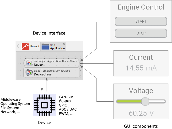
The following sections are intended to provide you an introduction and useful tips of how to add, implement and use Device Interfaces. To better understand the underlying concepts we also recommend you to read the chapter Integrating with the device.
Add a new Device Interface
In order to add a new Device Interface to your project, following steps are necessary. Please note, that Device Interfaces can exist in units only:
★First switch to the Composer page for the respective unit, where you want to add the new Device Interface.
★Then ensure that the Templates window is visible.
★In Templates window switch to the folder Device.
★In the folder locate the template Device Interface.
★Drag & Drop the template into the Composer window:
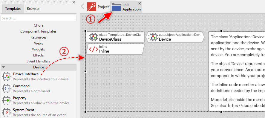
In the screenshot above you see that new added Device Interfaces consist of two members: a class and an autoobject. Within the class you will manage all the functionality needed for the GUI application and the underlying device to interact with each other. This is the implementation of the Device Interface. The autoobject, in turn, represents an instance of the Device Interface. Through this instance the GUI application can access and use the Device Interface functionality easily. The both members are also accompanied by an annotation providing helpful tips how to proceed. If undesired, you can select and delete the annotation.
The Inline Code member, in turn, is intended to incorporate to the project all relevant external dependencies like C header files, type declarations or even complete functions. In fact, whatever you put within the Inline Code member will be taken over during the code generation as it is. The implementation of the Device Interface can then access this code. If not necessary, you can select and delete the Inline Code member.
Name the Device Interface
The names of newly added Device Interfaces start per default with DeviceClass. That can lead to confusion when your application requires multiple, separate Device Interfaces to control the hardware, communicate via network with a remote service, etc. In such cases it is thus reasonable immediately after adding a new Device Interface to name it according to the corresponding function in your application (e.g. to NetworkDeviceClass). For this purpose:
★Press the key F2 or select the menu item .
★Enter the new name in the Inspector window.
With the above steps you rename the class intended to accommodate the implementation of the Device Interface. This class is additionally accompanied by an autoobject representing the instance of the Device Interface in question. Through this autoobject the GUI application can access and use the Device Interface. Therefore after renaming the class you should also adapt the name of this autoobject to be obvious. Per default this name starts with Device. Rename the autoobject so that it addresses its real function (e.g. NetworkDevice). For this purpose:
★First ensure, that the autoobject brick Device is selected.
★Press the key F2 or select the menu item .
★Enter the new name in the Inspector window.
Add middleware and other external code to the project
The intention of the Device Interface is a seamless integration with the underlying middleware or other device specific, external software. This can consist of libraries, *.C, *.C++, *.H or, in case of the WebGL target system, JavaScript files. In order to allow the Device Interface to use this external code you have to add all relevant declarations and external code fragments to Embedded Wizard project. You do this by adapting the Inline Code member found per default in the Device Interface template:
★Press the key Enter to open the member in the Code Editor.
★... or double click with the mouse on the Inline brick:
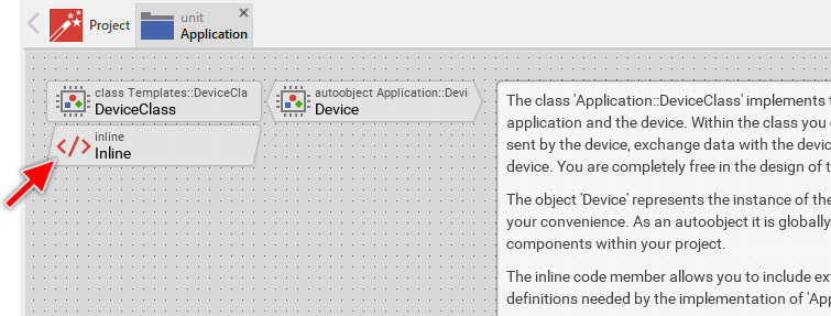
Thereupon the content of the Inline Code member is shown in the Code Editor window and you can edit it now. In fact, whatever you put within the Inline Code member will be taken over during the code generation as it is. Consequently, you can specify here all the C include files relevant for the integration with the underlying device. For example, you could include the API of some middleware. Also possible, you declare in-place all relevant data types and functions:
/* Include all relevant external header files. */ #include "middleware_api.h" /* ... or declare data types in-place. */ typedef struct { /* Some state information, etc. */ int Voltage; int Current; } Power_State; /* Similarly externally implemented functions can be pre-declared here. */ void GetPowerState( Power_State* aPowerState ); void SetMaxCurrent( int aMaxCurrent ); int GetMaxCurrent( void );
Middleware or other device specific, external software will expose their functionality by a concrete programming interface, an API. The structure of this API will differ from device to device. In some cases the API will already be perfectly suitable to be used from the Device Interface. In other cases the usage of the API will become difficult so single Device Interface operation will require invocations of multiple functions implemented in the external software and it will eventually need to collect the resulting values in data structures, etc.
Generally we don't recommend to access the external API directly from the Device Interface. Instead you should create a thin programming layer abstracting additionally the API. Within this layer you can encapsulate all the peculiarities of the underlying device. Once you have read the following sections of this chapter and understood the concept of the Device Interface, you should reflect about the functions and data structures needed to connect the both worlds: Device Interface on one side and external code on the other side. Doing this try to specify the functions so they correspond as good as possible to the operations imposed by the Device Interface. For example, if the Device Interface does implement a property MaxCurrent, it is reasonable to provide for this purpose in the separating interface a single function (e.g. SetMaxCurrent()) and invoke this function from the Device Interface whenever the property is changed by the GUI application.
The declarations of all resulting functions as well as of all relevant data types you can put in a header file and include this file in the above mentioned Inline Code member. In this manner Device Interface can use the functions and data types. By the way, separating the Device Interface and the external code by additional functions helps to avoid conflicts between homonymous type and function definitions existing eventually in the external code and Embedded Wizard.
The following sections explain diverse operations of the Device Interface and how to adapt them for a concrete application case. In all examples we use imaginary functions, we assume they are implemented as explained above to separate the Device Interface and the external code. In all examples we also assume, the necessary functions and data type declarations are correctly included in the Inline Code member.
Implement the Device Interface
Once you have added a new Device Interface to your project, you will implement it according to your needs. For this purpose, open the Device Interface class for editing:
★Press the key Enter to open the class in a new Composer page.
★... or double click with the mouse on the DeviceClass brick:
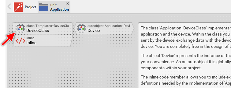
New added Device Interfaces contain already few methods suitable to handle the initialization and de-initialization of the interface. Following screenshot shows the default content of a new created Device Interface. In order to help you to start with your own adaptation, these members are explained in associated annotations. Furthermore each member is inline commented what can be seen in Inspector window after selecting the respective member.
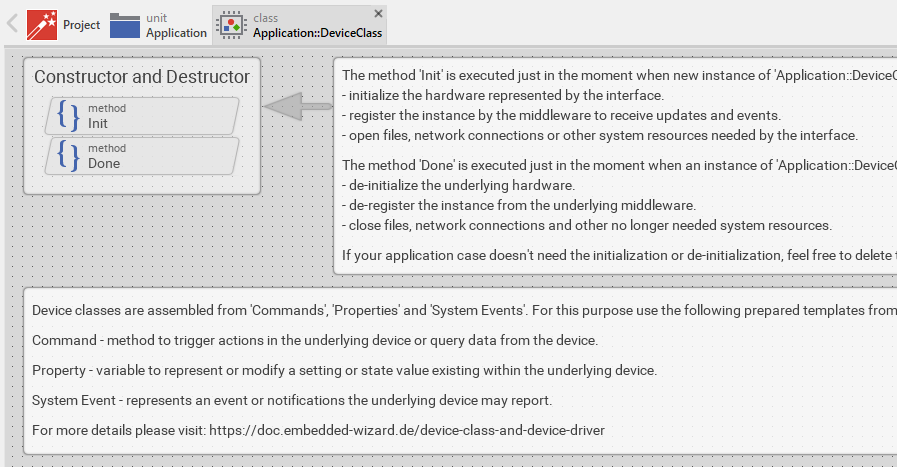
Since the per default contained Init and Done members exist for your convenience only, it is fully legitimate to select and delete those which are undesired. Similarly you can delete the annotations. To start from scratch with a completely empty Device Interface you can even select and delete all the members. Later, when implementing the Device Interface you will add new members to the class. Which members are appropriate does in fact depend on the kind of operation you intend to achieve as explained in the following table:
Icon |
Name |
Description |
|---|---|---|
|
The Command represents a certain action in your device, like Start Engine, Send Data to CAN-Bus Subscriber or Play Song X. The Command can also be used to query data stored actually in the device or received via network connection, e.g. Is Engine Running or Get Title of Current Playlist Song. Commands are triggered from the GUI to perform the respective operation in the device. |
|
|
The System Event represents a certain event in your device, like the notification Temperature Warning, Battery Charging Started or even Requested Data Is Available. System Events are triggered by the device. Thereupon the GUI application can react to the event and e.g. inform the user about the new situation. |
|
|
The Property represents a certain setting or a value in your device, like the voltage preset in a power supply device or the speed to display on the tachometer of an E-bike. The GUI application can read and modify the Properties similarly to variables. A modification can trigger respective operation in the device. The device, in turn, can update Properties with new values and thereupon trigger notifications within the GUI application. |
Whether you use Commands, System Events or Properties does depend on your particular application case and your preferences. There are no precise recommendations which of the members is the appropriate to be used for each case. In fact, many application cases can be implemented in different ways. Therefore, to give you an idea of the typical scenarios and their possible implementations we have prepared the following enumeration:
1. Trigger an operation in the device
This is the most common and simplest scenario. In response to a user interaction, the GUI application triggers an operation in the device, e.g. it starts an engine. The best appropriate member for this purpose is the Command. Also possible, but less evident, is the possibility to trigger an operation when the GUI application modifies a Property.
2. Synchronous query of data from the device
In this scenario, the GUI application queries some value from the device. This is not necessarily a value stored directly in the device. If necessary, the value can be requested via network connection or read from a file system, etc. In such case, the GUI application has to wait until the requested value is available.
The best appropriate member for this purpose is the Command. If the value is already stored in the device (e.g. within a variable), the access to the value can also be managed by using a Property.
3. Non-blocking (asynchronous) query of data from the device
In this scenario, the GUI application queries some value from the device and the query operation takes too long to wait for the results. This can be a request via slow network connection. Also possible is decoding of large image/video contents, etc.. In such case the GUI application triggers the request and continues the execution without waiting for its completion. The best appropriate member for this trigger operation is the Command.
As soon as the requested data is available, the device sends a System Event to the GUI application. Thereupon the application can pick up the now available value and proceed with it. To pick up the value the application can use another Command dedicated to query the value. Also possible, the requested value can be passed together in the context of the System Event. To react to the System Event, the GUI application uses the System Event Handler.
Providing of the requested data can also occur via Property associated to the value. In such case, as soon as the requested data arrives, the device updates the respective Property, which thereupon triggers a notification within the GUI application. When the GUI application reads the Property it gets the requested data. To react to an alternation of a Property, the GUI application can use the Property Observer. If your application uses widgets, these can be connected directly to Properties without writing a single line of code. Then, the widgets react to the alternations of the associated Properties automatically.
4. React to events generated by the device
In this scenario, the GUI application depends on events generated by the device. These can be simple status notifications or important, critical events. The best appropriate member for this purpose is the System Event. To react to the System Event, the GUI application uses the System Event Handler.
If there is a value associated to the event it is also practicable to use a Property for this purpose. As soon as the device updates the Property, the GUI application is notified automatically. To react to an alternation of a Property, the GUI application can use the Property Observer.
5. Modify setting variables in the device
In this scenario, the device manages setting or configuration parameters. These variables can be modified by the user via GUI and an alternation of a setting may trigger the device to perform an operation. In this case it is practicable to create the interface from Properties, one for each individual setting. A Properties can implement code to execute in the device when it is modified by the GUI application. If your application uses widgets, these can be connected directly to Properties without writing a single line of code.
An alternative approach is to use Commands for this purpose. In order to change a setting, the GUI application invokes the Command and provides to it the new value for the corresponding device setting. The implementation of the Command, in turn, takes care of all the operations to perform in the device.
6. Read setting variables from the device
In this scenario, the device manages setting or configuration parameters. The GUI application can access and evaluate these variables. In this case it is practicable to create the interface from Properties, one for each individual setting. These Properties reflect thereupon the values stored in the device and they remain valid as long as the device doesn't change them. If your application uses widgets, these can be connected directly to Properties without writing a single line of code. An alternative approach is to use Commands to query the setting. If the values can be changed by the device please see the next scenario.
7. React to changes of setting variables managed in the device
In this scenario, the device manages setting or configuration parameters. These variables can be modified by the device itself whereupon the GUI needs to be notified. In this case it is practicable to create the interface from Properties, one for each individual setting. When the device changes the value of a setting, it updates the corresponding Property with its new value. This triggers corresponding notifications within the GUI application. If your application uses widgets, these can be connected directly to Properties without writing a single line of code. Then, the widgets react to the alternations of the associated Properties automatically. Property Observers can also be used to react to alternations of Properties.
An alternative approach is to use Commands to query the settings and the System Events to get notified after the device has modified a setting. To react to the System Events, the GUI application uses the System Event Handler.
8. Track state variables managed in the device
In this scenario, the device manages state variables. These change dynamically at the runtime whereupon the device needs to notify the GUI. In this case it is practicable to create the interface from Properties, one for each individual state. When the device changes the value of a state, it updates the corresponding Property with its new value. This triggers corresponding notifications within the GUI application. If your application uses widgets, these can be connected directly to Properties without writing a single line of code. Then, the widgets react to the alternations of the associated Properties automatically. Property Observers can also be used to react to alternations of Properties.
An alternative approach is to use Commands to query the states and the System Events to get notified after the device has updated a state. To react to the System Events, the GUI application uses the System Event Handler.
Implement Device Interface initialization and de-initialization
Per default the new created Device Interface contains an Init and a Done method. These serve as so-called constructor and destructor. At the runtime Init is invoked automatically as soon as the Device Interface is instantiated. This is usually the case when a GUI component accesses the autoobject associated to the Device Interface for the first time. The Done method, in turn, is invoked when a Device Interface instance is disposed, means the autoobject is not referenced anymore by any existing GUI component.
You can edit the methods and implement there code to e.g. register/de-register the Device Interface instance by the middleware. If the Device Interface performs file system operations or exchange data via network, the method Init is ideal to open the file or establish the network connection. The method Done should close all used files, network ports and release system resources not needed anymore.
Manage multiple Device Interface classes
Depending on your application case it can be reasonable to implement several Device Interfaces instead of trying to put all functionality within a single one. Let's assume, your device is intended to control pump engines. It implements additionally functionality to exchange data via network connection and to store information on local file system. In such scenario, you could implement three separate Device Interfaces: Pump Engine Device Interface, Network Device Interface and File System Device Interface.
Manage multiple Device Interface instances
In order to access the functionality implemented in the Device Interface it is necessary to either create a new or query an existing instance of the respective Device Interface class. For your convenience such instance is provided implicitly when you add a new Device Interface to your project. It is represented by the global autoobject member named per default Device. The advantage of such global autoobject is that the application can access it from everywhere easily:
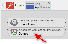
Having a unique instance of the Device Interface is the most common approach. In particular cases, however, it can be more appropriate to manage multiple instances of one and the same Device Interface. Let's assume, your device is intended to control three equal pump engines. Each engine can be individually started, stopped and its state can be queried. Usually, the corresponding Device Interface would implement three sets of Commands to start, stop and query the state of each pump engine, like Start Pump 1, Start Pump 2 and Start Pump 3.
Similar can be achieved with the Device Interface implemented to control a single pump engine. The individual engines are then represented by separate instances of the Device Interface. The following figure demonstrates this approach. In such case, to control e.g. the second pump engine the GUI application uses the corresponding PumpDevice2 instance:
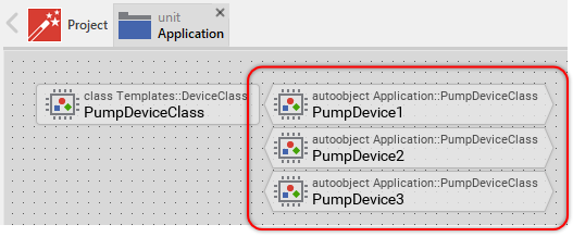
This approach expects, that the instances store some parameters identifying explicitly the corresponding pump engines. This can be achieved by adding an ordinary property member to the Device Interface class. The initialization value of such EngineId property addresses thereupon the corresponding engine. In the simplest case, the property could store an integer value 1, 2 or 3. When you select the autoobject representing a Device Interface instance, the Inspector window lists all properties belonging to it. Now you can initialize the EngineId property with the right value. For example, 2 in case of the instance controlling the second pump:

The implementation of the Device Interface class can evaluate the value stored in the EngineId property and e.g. relay it as parameter in all invocations to the underlying software running on the device and taking care of the communication with the pump engines. In this manner, the implementation of the Device Interface remains generic regardless of the number of existing instances.
Manage product specific Device Interface variants
With Embedded Wizard you can generate from one and the same project the code for different target systems. Accordingly, it is possible to develop a single GUI application intended to control different variants of your product or being adapted to different hardware/software revisions. While the GUI relevant parts remain platform independent in such case, the integration with the device can be specific depending on the product variant.
The integration with the device is encapsulated within the Device Interface. This includes all product variant specific adaptations. The first possible approach is thus to adapt the implementation of the common Device Interface to work correctly with all possible variants of your product. You could use for this purpose the Chora conditional compilation directives. Another, more sophisticated approach is to create variants of the Device Interface class correlating with the different variants or revisions of your product. The chapter Managing variants explains the underlying concepts. Summarized:
★You create first a Device Interface, as usual.
★You add to the interface all necessary Commands, System Events and Properties.
★For the new added members, you don't implement any functionality to communicate with the device.
★Derive a new class variant from the original Device Interface class.
★Configure the variant condition for the just derived class variant. If the variant selection occurs statically at the code generation time, use profiles for this purpose. If you want the functionality to change dynamically at the runtime of the application, use Styles as conditions.
★Now edit the class variant. Concrete override the methods added in the original Device Interface class and implement them with code particular for the corresponding product variant.
★For further product variants, add more class variants and adapt their implementation.
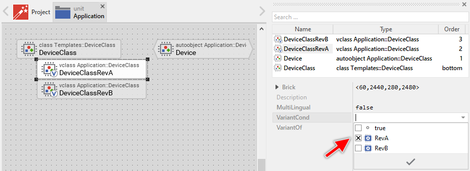
Following figure demonstrates a Device Interface implemented for two separate product revisions, Please note the variant condition of the selected class variant DeviceClassRevA. In this example, it is configured to depend on the profile member RevA. Accordingly, the implementation of the variant is taken over in your product only when you generate code with the profile RevA being selected:
Adapt Device Interfaces for Prototyping
The above section describes the possibility to implement various different versions of the Device Interface corresponding to the different variants or revisions of the real product. One of these implementations can be dedicated to work explicitly without any real device. It can, for example, simulate the behavior of the real hardware. Such approach is ideal to demonstrate the functionality of the GUI application without depending on any real hardware and by the way it allows you to test the GUI during the Prototyping.
★To achieve this, create an additional class variant from the original Device Interface class as explained in the section above.
★Configure the variant condition for the just derived class variant to depend on a profile intended for Prototyping (or demonstration) purpose only.
★Edit the class variant as explained in the section above. Concrete you can use timers and animation effects to simulate the behavior of the real device, trigger System Events, update Properties, etc. Use the trace statement to protocol the performed operations in the Log window.
★To use the variant ensure, that the specified profile is selected before you start the Prototyper.
For more sophisticated application cases, you can provide the necessary simulation within a dedicated intrinsic module. The intrinsic can even include software parts belonging originally to the middleware of the device. This could be, for example, a data base used in the device or a software module needed to communicate via network or CAN-bus. Doing this, the GUI application can access this functionality during Prototyping which makes it unnecessary to upload the GUI to the real device each time you want to test a new feature.
Create Device Interface instances dynamically
In order to access the functionality implemented in the Device Interface it is necessary to either create a new or query an existing instance of the respective Device Interface class. The preceding documentation focused on the second approach of using the existing, global autoobject provided per default with each Device Interface. However, if your application case it requires, you can create the instances dynamically by using the new operator. For example:
// Create the new instance var Application::DeviceClass device = new Application::DeviceClass; // Eventually configure the instance device.SomeSettings = ... // Use the instance, e.g. invoke a Command device.StartEngine();
Usually you don't need to create the instances dynamically unless you want them to reflect a dynamic characteristics of the underlying device. Let's assume, your device contains a hierarchical file system and the GUI application should enumerate the files and traverse the sub-directories stored on it. To achieve this, you can implement a Device Interface DirectoryClass. Through this interface you can query the number of files contained within a directory as well as you can enumerate these files. For example:
// Create a new instance to enumerate directory contents var Application::DirectoryClass device = new Application::DirectoryClass; // Configure the instance to enumerate the contents of the 'root' directory device.Path = "/"; // Query the number of files within the directory var int32 count = device.GetNoOfFiles(); var int32 fileNo = 0; // Print the names of all files contained within the directory for ( ; fileNo < count; fileNo = fileNo + 1 ) trace device.GetFile( fileNo );
Now let's assume, some of the files are sub-directories. In such case, you create a new instance of the DirectoryClass representing this sub-directory and use it to enumerate the files stored there. In the practice, you can implement this as a recursive algorithm. The following could be the implementation of such recursive method PrintFiles. The method expects in its parameter aPath the path to the corresponding directory on the file system:
// Create a new instance to enumerate directory contents var Application::DirectoryClass device = new Application::DirectoryClass; // Configure the instance to enumerate the contents of the directory // specified in the parameter 'aPath'. device.Path = aPath; // Query the number of files within the directory var int32 count = device.GetNoOfFiles(); var int32 fileNo = 0; // Print the names of all regular files and dive into sub-directories for ( ; fileNo < count; fileNo = fileNo + 1 ) { // If the entry is a sub-directory, invoke this code recursively with // the path addressing the sub-directory if ( device.IsDirectory( fileNo )) PrintFiles( aPath + device.GetFile( fileNo ) + "/" ); // In turn, regular files are simply printed on the console else trace device.GetFile( fileNo ); }
Implement a Device Driver
In particular cases when integrating the GUI application with the underlying device it can be reasonable to create an additional layer separating the GUI from the device. This additional abstraction is called Device Driver. Most of our provided Build Environments are already prepared with a template of such Device Driver. For example, please take a look at the module DeviceDriver.c found in the Build Environment. It contains following three functions:
/* The following function is executed at the initialization time of the GUI application. */ void DeviceDriver_Initialize( void ) { } /* The following function is executed shortly before the GUI application terminates. */ void DeviceDriver_Deinitialize( void ) { } /* The following function is executed periodically. The returned value has to indicated whether the function has processed any data (!=0) or not (==0). */ int DeviceDriver_ProcessData( void ) { return 0; }
The functions DeviceDriver_Initialize and DeviceDriver_Deinitialize are intended to perform code at startup and shutdown of the GUI application. Here you can, for example, setup operating system services essential for the communication with external data sources. Or, you initialize hardware components existing in your device. Please note, that initialization and deinitialization can also be handled by the Device Interface itself (see Implement Device Interface initialization and de-initialization).
The third function DeviceDriver_ProcessData is the most interesting one. This function is called periodically by the GUI thread (or task) and its aim is to check whether there are some important notifications to process, e.g. whether there are messages received from an external data source. If this is the case, the function should peek the message and depending on its content invoke a corresponding GUI function to trigger some event.
Before version 12, the above explained function DeviceDriver_ProcessData was the recommended approach to process externally generated messages in context of GUI thread/task as expected by Embedded Wizard. Starting with version 12, it is not necessary anymore to implement the above Device Driver. Instead external events can be fed by using the functions EwInvoke and EwInvokeCopy even if the event is generated in context of foreign thread or an interrupt service routine.
Example implementation of a Device Interface
Our Build Environments are delivered with an example demonstrating the implementation of the Device Interface and the integration with the device. Depending on the target system the implementation toggles GPIO ports and e.g. activates LEDs existing on the board, etc.. In case of so-called generic Build Environment, the examples limit to printf() the performed operations.
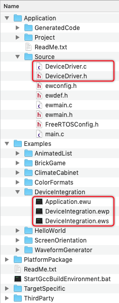
The Embedded Wizard project containing this example can be found in the folder Examples\DeviceIntegration within the respective Build Environment package. Furthermore, in the folder Application\Source you can find the files DeviceDriver.h and DeviceDriver.c. These implement diverse C functions needed by the Device Integration example. Following figure demonstrates the structure of a Build Environment and the locations where the mentioned files are found:
TIP
If you are implementing your own GUI application, the both DeviceDriver.h and DeviceDriver.c files are explicitly intended to be modified according to your individual integration aspects in your project.


