Getting started with STM MCUs: STM32U599 Discovery - NeoChrom
STM32U599 Discovery board (STM32U599J-DK).
The following article explains all necessary steps to create an Embedded Wizard UI application suitable for the STM32U599 Discovery board (STM32U599J-DK) or STM32U5A9 Discovery board (STM32U5A9J-DK) from STMicroelectronics.
Please follow these instructions carefully and step by step in order to ensure that you will get everything up and running on your target. In case you are not familiar with Embedded Wizard, please read first the chapter basic concepts and the Quick Tour tutorial to understand the principles of Embedded Wizard and the GUI development workflow.
Prerequisites
First, make sure you have all of the following items:
Hardware components
★STM32U599 Discovery board (STM32U599J-DK) or STM32U5A9 Discovery board (STM32U5A9J-DK) from STMicroelectronics
★USB cable to connect the board with your PC
Software components
★Embedded Wizard Studio Free or Embedded Wizard Studio Pro
If you want to use the Free edition of Embedded Wizard Studio please register on our website and download the software.
As a customer, please visit the Embedded Wizard Download Center (login/password required) and download Embedded Wizard Studio Pro.
★Embedded Wizard Build Environment for STM32U599 Discovery with NeoChrom graphics acceleration
To evaluate Embedded Wizard on the mentioned target, you can download the suitable Build Environment from the following link:
![]() STM32U599-Discovery-BuildEnvironment-V13.03.01.00.zip
STM32U599-Discovery-BuildEnvironment-V13.03.01.00.zip
As a customer, please visit the Embedded Wizard Download Center (login/password required) and download the latest version of the Build Environment and your licensed Platform Package libraries or source codes.
★STM32CubeProgrammer from STMicroelectronics
★Optional: STM32CubeIDE from STMicroelectronics
★Optional: IAR Embedded Workbench
★Optional: Keil MDK-ARM
★Optional: STM32CubeMX Initialization Code Generator
Installing Tools and Software
★Step 1: Install the latest version of Embedded Wizard Studio.
★Step 2: Install the STM32CubeProgrammer utility. Test the connection from PC to Discovery board and the proper installation of the USB drivers: Connect the Discovery board with your PC via USB (make sure to use the ST-LINK USB connector) and start the previously installed STM32CubeProgrammer. Select the green button and verify that the connection could be established successfully. Finally, close the STM32CubeProgrammer utility.
★Step 3: Unpack the provided Embedded Wizard Build Environment for STM32U599 Discovery to your local file system (e.g. C:\STM32\STM32U599-Discovery). Please make sure to use a short working folder path because STM32CubeIDE (to be more precise: Eclipse) has restrictions regarding the file path length.
★Step 4: Take a text editor and open the file FlashDownload.cfg that you will find in the subdirectory \Application\FlashDownload of the Build Environment. At the beginning of the file, the following environment variable has to be set to the installation path of the STM32CubeProgrammer utility:
•Stm32CubeProgrammerPath - Absolute path of your installed STM32CubeProgrammer utility (Step 2).
Exploring the Build Environment
The provided Embedded Wizard Build Environment for STM32U599 Discovery contains everything you need to create, compile, link and flash an Embedded Wizard UI application for the STM32U599 target. After unpacking, you will find the following subdirectories and files:
•StartGccBuildEnvironment.bat - This script file is provided to start a windows command line to build your GUI applications for the target.
•\Application - This folder contains ready-to-use projects to compile and link an Embedded Wizard generated UI application. They are used for all provided examples and they can be used to build your own UI applications.
•\FlashDownload - This folder contains a script to load the created binaries into the flash of your target by using the STM32CubeProgrammer tool. Don't forget to set the path of your installed STM32CubeProgrammer utility within the file FlashDownload.cfg.
•\GeneratedCode - This folder is used to receive the generated code from an Embedded Wizard UI project. All template projects are building the UI application out of this folder. You can create your own UI project and generate the code into the subdirectory \GeneratedCode without the need to adapt the project.
•\Project - This folder contains the prepared projects for GCC (make), IAR Embedded Workbench, Keil MDK-ARM and STM32CubeIDE.
•\Source - This folder contains the files main.c and ewmain.c. There you will find the initialization of the system and the main loop to drive an Embedded Wizard GUI application. The file ewconfig.h contains general configuration settings for the target system, like memory ranges and display parameter and configuration settings for the Embedded Wizard Graphics Engine and Runtime Environment. Additionally, this folder contains the device driver C/H files used for the DeviceIntegration example.
•\STM32CubeMX - This folder contains the STM32CubeMX project to change the STM32 hardware configuration (e.g. pin and peripheral configuration, clock tree settings). In case you generate the initalization code with STM32CubeMX, please ignore the generated project files and use the perpared project files from the \Project folder.
•\Examples\<ScreenSize> - This folder contains a set of demo applications prepared for a dedicated screen size (480x480 pixel). Each example is stored in a separate folder containing the entire Embedded Wizard UI project. Every project contains the necessary profile settings for the STM32U599 target. The following samples are provided:
•\HelloWorld - A very simple project that is useful as starting point and to verify that the entire toolchain, your installation and your board is properly working.
•\ColorFormats - This project demonstrates that every UI application can be generated for different color formats: RGB565, RGB888 and RGBA8888.
•\ScreenOrientation - This demo shows, that the orientation of the UI application is independent from the physical orientation of the display.
•\DeviceIntegration - This example shows the integration of devices into a UI application and addresses typical questions: How to start a certain action on the target? How to get data from a device?
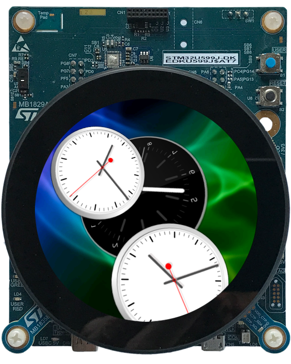
•\AnimatedWatch - The sample application AnimatedWatch implements a 3D animation with a different clock faces. This demo makes intensive usage of the Warp3D functionality.
•\BezierClock - The sample application BezierClock implements a fancy digital clock and timer application with animated digits. The application uses vector graphics to render dynamically the different digits for clock and timer. The change from one digit to another is handled by moving the vector points to get a smooth transition animation.
•\BrickGame - The sample application BrickGame implements a classic "paddle and ball" game. In the game, a couple of brick rows are arranged in the upper part of the screen. A ball travels across the screen, bouncing off the top and side walls of the screen. When a brick is hit, the ball bounces away and the brick is destroyed. The player has a movable paddle to bounce the ball upward, keeping it in play.
•\SmartThermostat - The SmartThermostat demo application shows the implementation of a fancy, rotatable temperature controller to adjust and display the nominal and actual temperature.
•\StarField - This simulation application implements a star field animation (space flight) with a variable number of images within the 3D space. The user can configure the eye distance and the animation speed. This demo makes intensive usage of the Warp3D functionality.
•\PlatformPackage - This folder contains the necessary source codes and/or libraries of the STM32 Platform Package: Several Graphics Engines for the different color formats (RGB565, RGB888 and RGBA8888) and the Runtime Environment (in the subdirectory \RTE).
•\TargetSpecific - This folder contains all configuration files and platform specific source codes. The different ew_bsp_xxx files implement the bridge between the Embedded Wizard UI application and the underlying board support package (STM32 hardware drivers) in order to access the display, the serial interface and the clock.
•\ThirdParty - This folder contains third-party source codes and tools:
•\gcc-arm-none-eabi - This folder contains a subset of the ARM GNU toolchain to compile the examples.
•\Make - This folder contains a make tool to build the entire GUI application via command line.
•\STM32Cube_FW_U5 - This folder contains the necessary subset of the STM32CubeU5 embedded software for STM32U5 series used for the Embedded Wizard UI applications (HAL, BSP, drivers, RTOS).
Creating the UI Examples
For the first bring up of your system, we recommend to use the example 'HelloWorld':
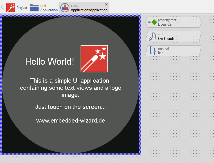
Example 'HelloWorld' within Embedded Wizard Studio.
The following steps are necessary to generate the source code of this sample application:
★Navigate to the directory \Examples\<ScreenSize>\HelloWorld.
★Open the project file HelloWorld.ewp with your previously installed Embedded Wizard Studio. The entire project is well documented inline. You can run the UI application within the Prototyper by pressing Ctrl+F5.
★To start the code generator, select the menu items - or simply press F8. Embedded Wizard Studio generates now the sources files of the example project into the directory \Application\GeneratedCode.
Compiling, Linking and Flashing
The following steps are necessary to build and flash the Embedded Wizard UI sample application using the GCC ARM embedded toolchain:
★Navigate to the top level of the Build Environment.
★Open StartGccBuildEnvironment.bat - as a result, a windows command line window should open. In case there are error messages, please edit the file and double-check the path settings.
★Now start compiling, linking and flashing:
make make install
If everything works as expected, the application should be built and flashed to the STM32U599 target.
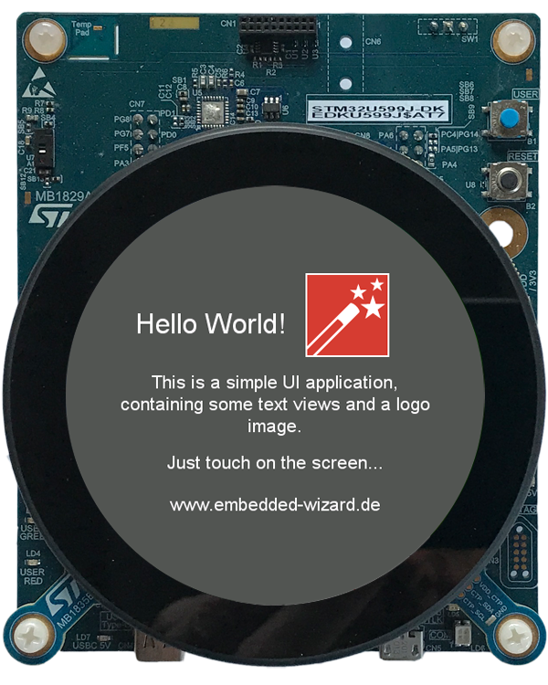
Example 'HelloWorld' running on STM32U599 Discovery board.
All other examples can be created in the same way: Just open the desired example with Embedded Wizard Studio, generate code and rebuild the whole application using simply:
make install
Creating your own UI Applications
In order to create your own UI project suitable for the STM32U599 target, you can create a new project and select the STM32U599 Discovery project template:
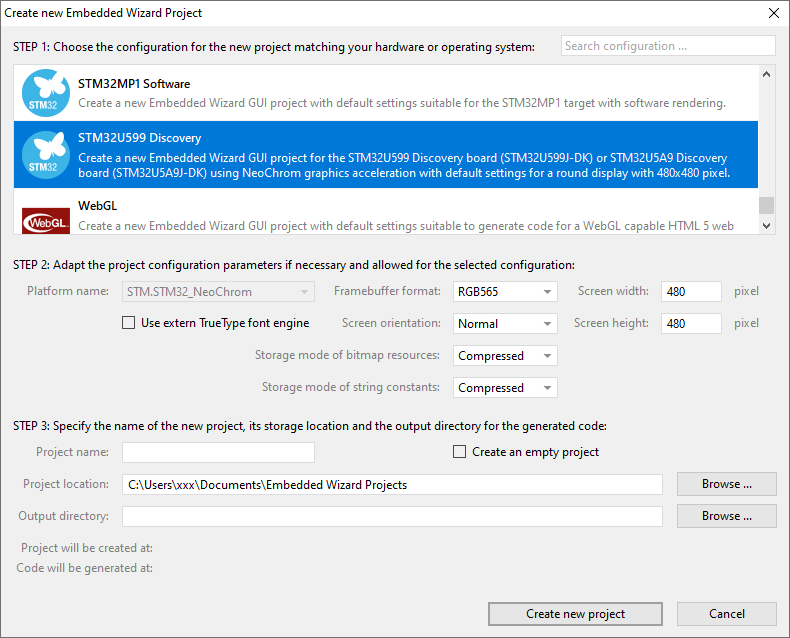
As a result you get a new Embedded Wizard project, that contains the necessary Profile attributes suitable for the STM32U599 Discovery board:
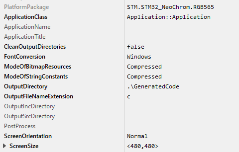
The following profile settings are important for your target:
★The attribute PlatformPackage should refer to the STM32 NeoChrom Platform Package. Please note, that for STM32U599 only the color formats RGB565, RGB888 or RGBA8888 can be used.
★The attribute ScreenSize should correspond to the display size of the STM32U599 Discovery board.
★The attributes ModeOfBitmapResources and ModeOfStringConstants can be set to DirectAccess in case that the resources should be taken directly from flash memory. By default these attributes are set to Compressed.
★The attribute OutputDirectory should refer to the \Application\GeneratedCode directory within your Build Environment. By using this template, it will be very easy to build the UI project for your target.
★The attribute CleanOutputDirectories should be set to true to ensure that unused source code within the output directory \Application\GeneratedCode will be deleted.
★The attribute PostProcess should refer to \Application\Project\EWARM\EWARM_ew_post_process.cmd if you are working with IAR Embedded Workbench or to \Application\Project\MDK-ARM\MDK-ARM_ew_post_process.cmd if you are working with Keil MDK-ARM. In case of the GCC ARM embedded toolchain leave it blank
Now you can use the template project in the same manner as it was used for the provided examples to compile, link and flash the binary.
After generating code, please follow these steps, in order to build your own UI application:
★Start the batch file 'StartGccBuildEnvironment.bat'. Again, a windows command line window should open.
★Start compiling, linking and flashing:
make install
Most of the project settings are taken directly out of the generated code, like the color format or the screen orientation. Only a few additional settings can be configured directly within the Makefile, like the usage of an external flash memory. All other settings can be made directly within the file ewconfig.h, which contains general configuration settings for the target system.
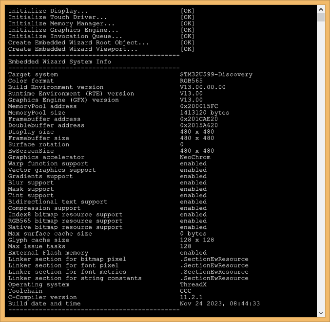
Console output
In order to receive error messages or to display simple debug or trace messages from your Embedded Wizard UI application, a serial terminal like 'Putty' or 'TeraTerm' should be used.
★As soon as you connect your STM32U599 target with the PC via USB, a STMicroelectronics STLink Virtual COM Port (COMx) appears within your system device list. Open the device manager to get the number of the installed COM port.
★Now you can open your terminal application and connect it via COMx with the following settings: 115200-8-N-1
This terminal connection can be used for all trace statements from your Embedded Wizard UI applications or for all debug messages from your C code.
Using IAR Embedded Workbench
If you want to use the IAR Embedded Workbench instead of the GCC ARM embedded toolchain, please follow these instructions:
The subdirectory \Application\Project\EWARM contains a template project that is commonly used for all provided Embedded Wizard examples. All Embedded Wizard examples will store the generated code within the common \Application\GeneratedCode folder.
The generated code of an Embedded Wizard example is imported automatically to the IAR Embedded Workbench project using the Project Connection mechanism.
To establish this automatic project import a post process has to be added to the Profile settings within Embedded Wizard Studio:
★Open the desired Embedded Wizard example project.
★Select the Profile and set the attribute PostProcess to the file ..\..\Application\Project\EWARM\EWARM_ew_post_process.cmd.
After the Embedded Wizard code generation the installed post process will generate a ewfiles.ipcf file, that controls the import to the IAR Embedded Workbench project.
After returning to IAR Embedded Workbench, the latest generated code and the suitable Embedded Wizard Platform Package will be imported to the IAR Embedded Workbench project (depending on the color format and the screen orientation selected in the Embedded Wizard Profile).
If the color format or the screen orientation was changed, please do a complete rebuild of the IAR Embedded Workbench project.
Using Keil MDK-ARM
If you want to use the Keil MDK-ARM toolchain instead of the GCC ARM embedded toolchain, please follow these instructions:
The subdirectory \Application\Project\MDK-ARM contains a template project that is commonly used for all provided Embedded Wizard examples. All Embedded Wizard examples will store the generated code within the common \Application\GeneratedCode folder.
The generated code of an Embedded Wizard example is imported automatically to the Keil MDK-ARM project using the CMSIS PACK mechanism.
The following steps are needed to establish this automatic project import:
★Install Tara.Embedded_Wizard_Launcher.x.x.x.pack by double clicking. You will find the file within the subdirectory \Application\Project\MDK-ARM.
★Open the desired Embedded Wizard example project.
★Select the Profile and set the attribute PostProcess to the file ..\..\Application\Project\MDK-ARM\MDK-ARM_ew_post_process.cmd.
After the Embedded Wizard code generation the installed post process will generate a ewfiles.gpdsc file, that controls the Keil MDK-ARM project import.
In Keil MDK-ARM a dialog appears: "For the current project new generated code is available for import". After confirmation, the latest generated code and the suitable Embedded Wizard Platform Package will be imported to the Keil MDK-ARM project (depending on the color format and the screen orientation selected in the Embedded Wizard Profile).
If the color format or the screen orientation was changed, please do a complete rebuild of the Keil MDK-ARM project.
Using STM32CubeIDE
If you want to use the STM32CubeIDE toolchain instead of the GCC ARM embedded toolchain, please follow these instructions:
The subdirectory \Application\Project\STM32CubeIDE contains a template project that is commonly used for all provided Embedded Wizard examples. All Embedded Wizard examples will store the generated code within the common \Application\GeneratedCode folder.
The following steps are needed to establish this automatic project import:
★Open the desired Embedded Wizard example project.
★Select the Profile and set the attribute PostProcess to the file ..\..\Application\Project\STM32CubeIDE\STM32U599-Discovery\STM32CubeIDE_ew_post_process.cmd.
After the Embedded Wizard code generation the installed post process will adapt the .cproject XML file. All necessary libraries and include paths (depending on the color format and screen rotation) will be set automatically.
The given STM32CubeIDE example under \Application\STM32CubeIDE contains a workspace which has all adaptions for an Embedded Wizard project. For using this within STM32CubeIDE do following steps:
★Open STM32CubeIDE and select the directory \Application\Project\STM32CubeIDE as workspace directory.
★To import the C project, select the menu item and choose General - Existing Projects into Workspace and press Next.
★Choose Select root directory - Browse and select the directory \Application\Project\STM32CubeIDE\STM32U599-Discovery.
★Press Finish.
★To compile the project press the Build button (hammer symbol) within the toolbar.
★Press the Run or Debug button within the toolbar to start the application on the target.
If the color format or the screen orientation was changed, please do a clean in STM32CubeIDE.
Release notes
The following section contains the version history of the Build Environment (including Graphics Engine and Runtime Environment) for STM32U599 Discovery. These release notes describe only the platform specific aspects - for all general improvements and enhancements please see the Embedded Wizard release notes.
Version 13.00.00.00
★Using Graphics Engine (GFX) and Runtime Environment (RTE) V13.00.
★Using STM32CubeMX V6.8.0.
★Using STM32CubeProgrammer V2.14.0.
★Using STM32CubeU5 Firmware Package V1.3.0.
★Using STM32NeoChromSDK V3.0.1.
★Using Arm GNU Toolchain V11.2-2022.02.
★Using IAR Embedded Workbench 9.40.2, IAR C/C++ Compiler V9.40.2.374/W64 for ARM.
★Using Keil MDK-ARM Professional Version 5.38.0.0, ARM Compiler 6.19 (armclang).
★Using STM32CubeIDE V1.13.2.
★Known Issue: The project cannot be compiled with Keil MDK-ARM when initialization code is generated by using the latest STM32CubeMX V6.9.2.
★Known Issue: The project does not work with latest STM32NeoChromSDK V3.1.0.
Version 13.00.00.01
★Changed to STM32CubeMX V6.9.2.
★Bug-fix for Keil MDK-ARM project - now it can be compiled when initialization code is generated by using STM32CubeMX V6.9.2.
Version 13.01.00.00
★Using Graphics Engine (GFX) and Runtime Environment (RTE) V13.01.
★Bug-fix: Crash with Shadow view displayed with rounded corners on target systems configured for screen orientation 90 or 270 degree.
★Bug-fix: Crash with Filled Path and Stroked Path views configured to buffer the rasterized image on target systems configured for screen orientation 90 or 270 degree.
★Bug-fix: Crash with Filled Path Bitmap and Stroked Path Bitmap on target systems configured for screen orientation 90 or 270 degree.
Version 13.03.00.00
★Using Graphics Engine (GFX) and Runtime Environment (RTE) V13.03.
★Bug-fix: Crash occurred during Garbage Collection when 64-bit data members are used. For more details concerning the fixed error see Known issues. Please don't forget to update your Build Environment and Platform Package modules!
Version 13.03.01.00
★Rebuild libraries due to separate support of NeoChrom and NeoChrom VG.
★Using STM32CubeProgrammer V2.16.0.
★Using STM32CubeIDE V1.15.1.