Platform Integration: Getting started with STM32F412 Discovery
STM32F412 Discovery board.
The following article explains all necessary steps to create an Embedded Wizard UI application suitable for the STM32F412 Discovery board. Please follow these instructions carefully and step by step in order to ensure that you will get everything up and running on your target. Moreover, this article assumes, that you are familiar with the basic concepts of Embedded Wizard.
Prerequisites
First of all, you need the following hardware components:
★STM32F412 Discovery board from STMicroelectronics
★USB cable to connect the board with your PC
Make sure that you have got the following software packages:
★Embedded Wizard Studio (Evaluation Edition, Starter Edition or Professional Edition)
★Embedded Wizard STM32 Platform Package
TIP
If you want to use the Evaluation Edition of Embedded Wizard Studio and the STM32 Platform Package, please register on our website and select the target STM32F412 Discovery. Then you can download the above software packages.
Installing Tools and Software
★Step 1: Install the latest version of Embedded Wizard Studio.
★Step 2: Install the Embedded Wizard STM32 Platform Package.
★Step 3: Download the STM32 ST-LINK utility and install it. Test the connection from PC to Discovery board and the proper installation of the USB drivers: Connect the Discovery board with your PC via USB (make sure to use the ST-LINK USB connector) and start the previously installed STM32 ST-LINK utility. Select the menu item and verify that the connection could be established successfully. Finally, close the STM32 ST-LINK utility.
★Step 4: Create a common STM32 project directory (e.g. \STM32) at any location in your local file system (e.g. in {UserDocumentFolder}).
IMPORTANT
Please take care to install the following software packages or sources into this common project folder by using exactly the recommended subdirectories!
If you follow these instructions you can just take the provided makefiles and configurations as they are. Otherwise, you need to adapt some paths.
★Step 5: Download the latest version (Windows ZIP) of the GCC ARM embedded toolchain and unpack it into the subdirectory {UserDocumentFolder}\STM32\gcc-arm-none-eabi For details concerning the toolchain, please have a look into the Release Note file on their website.
★Step 6: Download the latest version of the STM32CubeF4 embedded software for STM32F4 series and unpack it into the subdirectory {UserDocumentFolder}\STM32\STM32Cube_FW_F4
★Step 7: Download the latest version of the Embedded Wizard Build Environment for STM32F412 Discovery and unpack it into the subdirectory {UserDocumentFolder}\STM32\STM32F412-Discovery
As a result, you should now have the following directory structure:
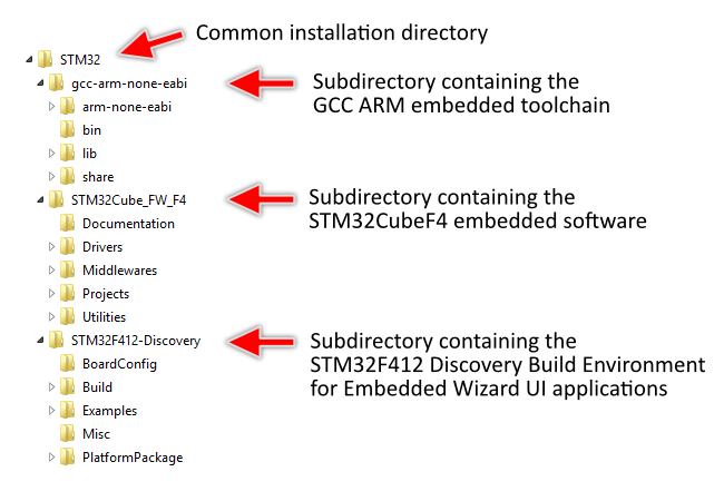
Exploring the Build Environment
The provided Embedded Wizard Build Environment for STM32F412 Discovery contains everything you need to create, compile, link and flash an Embedded Wizard UI application for the STM32F412 target. After unpacking, you will find the following subdirectories and files:
•\BoardConfig - This folder contains all configuration files and platform specific source codes.
•\Build - This folder contains the necessary stuff to build your UI application: the make utility and the script file StartBuildEnvironment.bat to start a windows command line to build the application.
•\Examples - This folder contains a set of demo applications. Each example is stored in a separate folder and contains an Embedded Wizard UI project, the necessary source code (e.g. main.c) and the necessary makefile to build the demos. Every Embedded Wizard project contains already the necessary profile settings for the STM32F412 target. The following samples are provided:
•\HelloWorld - A very simple project that is useful as starting point and to verify that the entire toolchain, your installation and your board is properly working. The subdirectory \EmWiProject contains the Embedded Wizard project file.
•\ColorFormats - This project demonstrates that every UI application can be generated for different color formats: RGB565, Index8 and LumA44.
•\ScreenOrientation - This demo shows, that the orientation of the UI application is independent from the physical orientation of the display.
•\DeviceIntegration - This example shows the integration of devices into a UI application and addresses typical questions: How to start a certain action on the target? How to get data from a device?
•\Template - This is just a template to build your own UI applications. It contains a main.c file and a makefile. You can create your own UI project and generate the code into the subdirectory \GeneratedCode.
•\Misc - This folder contains some helper modules for printing debug messages and the memory manager used for the Embedded Wizard UI applications.
•\PlatformPackage - This folder contains the necessary source codes and/or libraries of the STM32 Platform Package: Several Graphics Engines for the different color formats (RGB565, Index8 and LumA44) and the Runtime Environment (in the subdirectory \RTE).
If you have installed the above components in different locations as described, please adapt the makefile and the scripts accordingly.
Creating the UI Examples
For the first bring up of your system, we recommend to use the example 'HelloWorld':
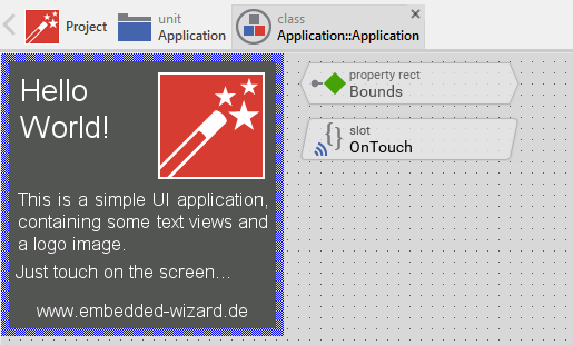
Example 'HelloWorld' within Embedded Wizard Studio.
The following steps are necessary to generate the source code of this sample application:
★Navigate to the directory \Example\HelloWorld\EmWiProject.
★Open the project file HelloWorld.ewp with your previously installed Embedded Wizard Studio. The entire project is well documented inline. You can run the UI application within the Prototyper by pressing Ctrl+F5.
★To start the code generator, select the menu items - or simply press F8. Embedded Wizard Studio generates now the sources files of the example project into the subdirectory \STM32.
Compiling, Linking and Flashing
The following steps are necessary to build and flash the Embedded Wizard UI sample application:
★Navigate to the directory \Build.
★Open StartBuildEnvironment.bat - as a result, a windows command line window should open. The starting directory location is \Examples.
★Navigate to the subdirectory \HelloWorld and start compiling, linking and flashing:
cd HelloWorld make make install
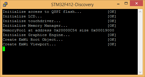
If everything works as expected, the application should be built and flashed to the STM32F412 target.
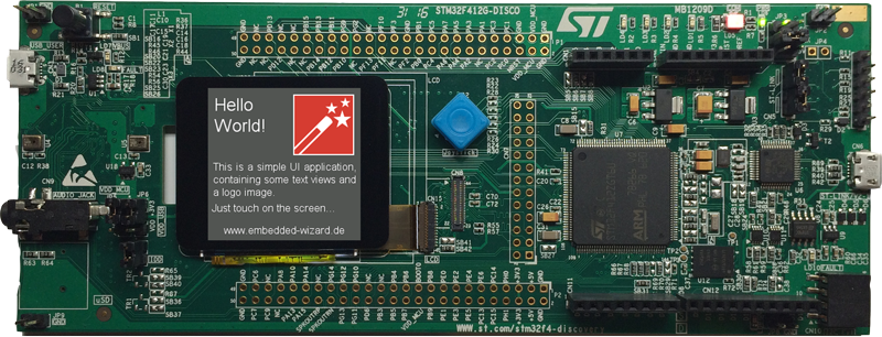
Example 'HelloWorld' running on STM32F412 Discovery board.
All other examples can be created in a similar manner. Please follow the instructions of the ReadMe.txt files that are located within every example.
Creating your own UI Applications
In order to create your own UI project suitable for the STM32F412 target, you can create a new project and select the STM32F412 Discovery project template:
As a result you get a new Embedded Wizard project, that contains the necessary Profile attributes suitable for the STM32F412 Discovery board:
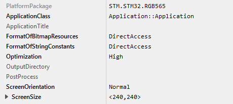
The following profile settings are important for your target:
★The attribute PlatformPackage should refer to an installed STM32 Platform Package. Please note, that for STM32F412 only the color formats RGB565, Index8 or LumA44 can be used.
★The attribute ScreenSize should correspond to the display size of the STM32F412 Discovery board.
★The attributes FormatOfBitmapResources and FormatOfStringConstants should be set to DirectAccess. This ensures that the resources are taken directly from flash memory.
★The attribute OutputDirectory should refer to the \Examples\Template\GeneratedCode directory within your Build Environment. By using this template, it will be very easy to build the UI project for your target.
Working with the Template
If you want to compile and link your own UI application, you can use the provided template (\Examples\Template) to build the application. This template is prepared to compile any UI application that is generated into the subdirectory \GeneratedCode.
After generating code, please follow these steps, in order to build your own UI application:
★Start the batch file 'StartBuildEnvironment.bat'. Again, a windows command line window should open. The starting directory location is \Examples.
★Navigate to the subdirectory \Template and start compiling, linking and flashing:
cd Template make make install
This template can be configured easily according your needs by changing the provided flags within the Makefile. These are the most important system settings that can be adapted:
•Color format of the framebuffer
•Color format of the Graphics Engine (which has to correspond to the color format of the PlatformPackage used within your UI project)
•Usage of screen rotation (which has to correspond to the ScreenOrientation used within your UI project)
•Usage of QSPI flash memory
•Usage of FreeRTOS operating system
Console output
In order to receive error messages or to display simple debug or trace messages from your Embedded Wizard UI application, a serial terminal like 'Putty' or 'TeraTerm' should be used.
★As soon as you connect your STM32F412 target with the PC via USB, a STMicroelectronics STLink Virtual COM Port (COMx) appears within your system device list. Open the device manager to get the number of the installed COM port.
★Now you can open your terminal application and connect it via COMx with the following settings: 115200-8-N-1
This terminal connection can be used for all trace statements from your Embedded Wizard UI applications or for all debug messages from your C code.