Using Graphic objects: Stroked Path Bitmap
The Stroked Path Bitmap object represents an ALPHA8 off-screen bitmap filled with the outline of a graphical shape according to provided vector path data. The Stroked Path Bitmap object can be used wherever ALPHA8 bitmaps are expected in your application. For example, it can be associated to a Filter Image view and act there as the mask bitmap. When at the runtime the provided path data changes, the content of the Stroked Path Bitmap is automatically updated, causing in turn an update in all associated views like the Filter Image view. The path data can be composed of line segments, Bézier curves and elliptical arcs. Several paths can be combined together in order to describe complex shapes.
Please note, Stroked Path Bitmap represents the bitmap only. To display its contents on the screen you have to assign the Stroked Path Bitmap object to an image view. If all you want to do is to display the outline of the shape, it may be more convenient to use the Stroked Path view instead of the here described bitmap object. The bitmap object is convenient only wherever the bitmap itself is needed (e.g. as mask in the Filter Image view).
The following sections are intended to provide you an introduction and useful tips of how to deal with the Stroked Path Bitmap. For the complete reference please see the documentation of the Graphics::StrokePath class.
CAUTION
Please consider, that each Stroked Path Bitmap object reserves memory for an internal bitmap to store the resulting graphical shape inside. The size of the bitmap corresponds to the size configured in the particular Stroked Path Bitmap object. Since the bitmap is stored in ALPHA8 format, the bitmap will occupy 1 byte per pixel. For example, a 300x200 pixel large Stroked Path Bitmap will occupy ~60 KB RAM. Thus, if RAM is a scarce resource in your target device, you should use the Stroked Path Bitmap objects with prudence.
Add new Stroked Path Bitmap
To add a new Stroked Path Bitmap just at the design time of a GUI component do following:
★First ensure that the Templates window is visible.
★In Templates window switch to the folder Resources.
★In the folder locate the template Stroked Path Bitmap.
★Drag & Drop the template into the Composer window:
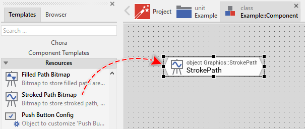
★Eventually name the new added Stroked Path Bitmap object.
Inspect the Stroked Path Bitmap
As long as the Stroked Path Bitmap object is selected you can inspect and modify its properties conveniently in the Inspector window as demonstrated with the property FrameSize in the screenshot below:
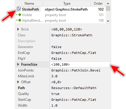
This is in so far worth mentioning as all following sections describe diverse features of the Stroked Path Bitmap by explicitly referring to its corresponding properties. If you are not familiar with the concept of a property and the usage of Inspector window, please read first the preceding chapter Compositing component appearance.
Connect the Stroked Path Bitmap to a view
The Stroked Path Bitmap stores the rasterized graphical shape in an internal ALPHA8 bitmap. In order to display this bitmap on the screen you have to connect the Stroked Path Bitmap object to one of the image views. Accordingly, the view will display the bitmap similarly to how regular static Bitmap resources are displayed.
To connect a Stroked Path Bitmap to a view you have to assign this object to the adequate property of the affected view (e.g. to the Bitmap property). With the Inspector Assistant you can conveniently select the right Stroked Path Bitmap object when you edit the initialization expression for the property. The following example demonstrates how you assign the Stroked Path Bitmap object to the property MaskBitmap of a Filter Image view:
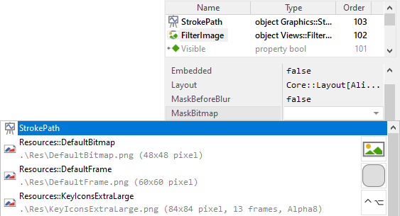
As soon as you have connected the both, the information provided in the Stroked Path Bitmap object is used by the view. If desired, you can assign the same object to several views. If during the runtime of the application, the content of the Stroked Path Bitmap object changes, all associated views are updated automatically.
Configure the Stroked Path Bitmap
Each Stroked Path Bitmap manages internally an off-screen ALPHA8 bitmap where the resulting (rasterized) graphical shape is stored. The size (width x height) of this bitmap is configured by using the property FrameSize. Consequently, if you configure the Stroked Path Bitmap with the size <200,100>, the bitmap will be able to store 200x100 pixel large graphical shapes. Parts of the graphical shape lying beyond this border are simply clipped.
CAUTION
Since the internally used off-screen bitmap is stored in ALPHA8 format, the bitmap will occupy 1 byte per pixel. For example, a 300x200 pixel large Stroked Path Bitmap will occupy ~60 KB RAM. Thus, if RAM is a scarce resource in your target device, you should use the Stroked Path Bitmap objects with prudence.
Provide path information for the Stroked Path Bitmap object
In order to rasterize a graphical shape in the Stroked Path Bitmap object, you have to provide the corresponding path information. You can consider the path as a list of connected straight line segments (so-called edges) describing precisely the outline to draw. Depending on the application case the path may consist of few or even hundreds of edges. In this manner you describe primitive (e.g. triangles) or even complex shapes (e.g. circles, rings, Bézier curves or polygons).
To provide the path information you use a Path Data object. Usually you will add such object to your component, you will implement code to fill this object with your particular path information (the lines, arcs, Bézier curves, etc.) and finally you will assign the so prepared object to the property Path of the affected Stroked Path Bitmap object. With the Inspector Assistant you can conveniently select the right object when you edit the initialization expression for the property Path. For example:
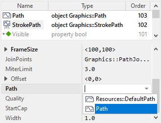
As soon as you have connected the both, the information provided in the Path Data object is processed by the Stroked Path Bitmap. If desired, you can assign the same Path Data object to several Stroked Path Bitmap (or Filled Path Bitmap) objects. If during the runtime of the application, the content of the Path Data object changes, all associated bitmap objects are updated automatically.
Please note, newly added Stroked Path Bitmaps are using the default Path Data object Resources::DefaultPath describing a simple pie segment. In the practice you will always manage your own path objects containing your particular path information. In any case you should avoid to modify the contents of the Resources::DefaultPath object.
In particular cases, when the desired shape is an ellipse, ring, pie segment, circle segment, etc. you can use the more convenient Arc Path Data object. With this object you don't need to implement any code to prepare the path data. Instead, you simply configure the properties of the Arc Path Data object determining so e.g. the desired radiuses of the ellipse, its start and end angles, and so far.
SEE ALSO
Using the Path Data object to create complex polygons and shapes.
Using the Arc Path Data object to create circular polygons, arcs, pie segments, etc..
Determine the origin position for the path coordinates
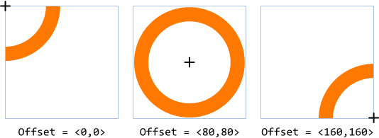
Per default, the coordinates provided in the associated path object are rasterized relative to the top-left corner of the Stroked Path Bitmap. This corner corresponds thus to the origin of the path own coordinate system (0,0). By modifying the property Offset you can specify other position within the area of the Stroked Path Bitmap where to map the origin of this coordinate system. In other words, changing the property Offset causes the shape to be rasterized at different position within the area of the Stroked Path Bitmap.
Let's assume, the associated path object describes a circle with its center lying at the origin of the path own coordinate system (0,0). Depending on how the property Offset is configured, the circle appears at different positions within the Stroked Path Bitmap as demonstrated in the following screenshot. For visualization purpose, the black cross indicates the center of the path coordinate system and the thin blue frames are borders of the respective Stroked Path Bitmaps. Please note, parts of a shape lying outside of the bitmap's area are clipped and not visible:
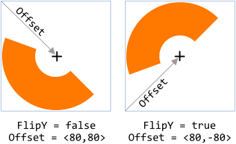
Originally the positive Y-axis of the path coordinate system points downwards, which corresponds to how other positions or coordinates are treated in Embedded Wizard. By initializing the property FlipY with the value true, the Stroked Path Bitmap mirrors vertically the path coordinate system resulting in the Y-axis pointing upwards, which is more natural for mathematical application cases. The shape described by the path appears accordingly mirrored. Furthermore, with this alternation the effect of the property Offset changes, so that it specifies the position where to map the origin of the path coordinate system relative to the bottom-left corner of the view. The following screenshot demonstrates this effect:
Specify the thickness of the stroked path
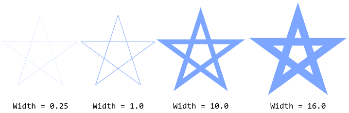
To specify the thickness of the stroked path you simply use the property Width. It accepts floating-point values permitting you to change the width with sub-pixel precision. For example, to rasterize a path with 10.75 pixel thickness, you assign the value 10.75 to this property. The following figure demonstrates the effect:
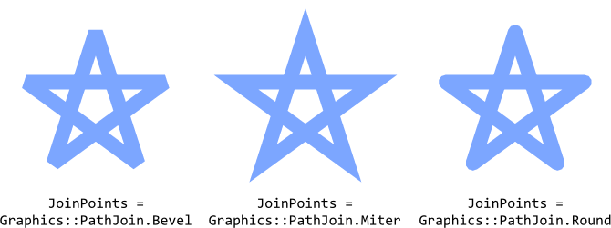
Control the appearance of join points between path edges
The Stroked Path Bitmap supports three different modes how the connection points between two consecutive path edges (the path corners) should be rasterized. You select the desired mode by initializing the property JoinPoints with the appropriate value. The following table provides an overview of the possible values:
Mode |
Description |
|---|---|
Graphics::PathJoin.Bevel |
The path segments are joined by connecting their outside edges with a single straight line segment. This is the default mode. |
Graphics::PathJoin.Miter |
The path segments are joined by extending their outside edges until they intersect. |
Graphics::PathJoin.Round |
The path segments are joined by rounding the corners lying in between. The diameter of the used circle corresponds to the thickness of the stroked path. |
When using the mode Miter you should consider the further property MiterLimit. This property determines the maximum ratio between the resulting length of the miter and the half of the path thickness. If this limit is exceeded, the affected corner is rasterized with the Bevel mode instead of Miter. With MiterLimit is ensured, that outside edges of a very sharp corner are not prolongated excessively. The following figure demonstrates the effect of the three modes:
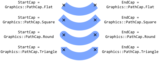
Control the appearance of caps at the ends of the stroked path
The Stroked Path Bitmap supports four different modes how to raster the start and the end cap of an opened path. You select the desired modes by initializing the properties StartCap and EndCap with appropriate values. In this manner you can configure the start and end caps individually. The following table provides an overview of the possible values:
Mode |
Description |
|---|---|
Graphics::PathCap.Flat |
The path caps are squared off just at the corresponding path cap position. This is the default mode. |
Graphics::PathCap.Square |
The path caps are extended by the half of the thickness of the stroked path and then squared off. |
Graphics::PathCap.Round |
The path caps are extended by the half of a circle with diameter equal to the thickness of the stroked path. |
Graphics::PathCap.Triangle |
The path caps are extended by a triangle with height of the half of the thickness of the stroked path. |
The following figure demonstrates the effect of the four modes. Please note the small black crosses indicating the positions where the path starts and ends:
Control the quality of the stroked path
The Stroked Path Bitmap rasterizes the shape per default with enabled anti-aliasing. This produces the best possible results. If not desired, with the property Quality you can disable this mode. For this purpose initialize Quality with the value false. The following figure demonstrates the results depending on the current setting of the property:

Embedded Wizard own implementation to rasterize vector graphics calculates with 4x anti-aliasing, which means that every pixel is divided in 4 sub-pixel vertically and 4 sub-pixel horizontally. If the vector graphic is rasterized by using target own graphics subsystem (e.g. GPU), the resulting anti-aliasing depends on the implementation of this subsystem. In particular cases (e.g. in case of the WebGL Platform Package) the anti-aliasing can't be deactivated.
TIP
Despite the advantages, you should consider, that with enabled anti-aliasing the rasterization operations are more computing intensive. Thus, if your target device is not powerful nor doesn't provide any dedicated graphics hardware to rasterize vector graphics, setting the property Quality to the value false may improve the performance.