Getting started with STM32: STM32F407 Discovery
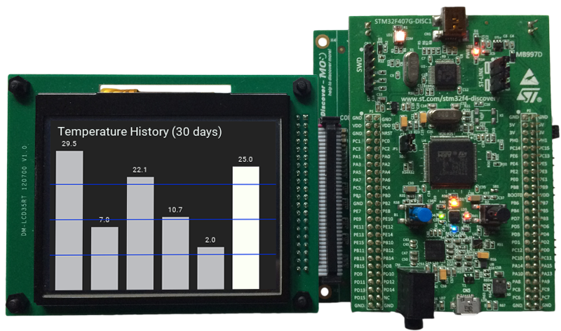
STM32F407 Discovery board (STM32F407G-DISC1) with STM32F4DIS-BB base board and STMF4DIS-LCD display module.
The following article explains all necessary steps to create an Embedded Wizard UI application suitable for the STM32F407 Discovery board. Please follow these instructions carefully and step by step in order to ensure that you will get everything up and running on your target. Moreover, this article assumes, that you are familiar with the basic concepts of Embedded Wizard.
Introduction: External display controller and partial display updates
Since the STM32F407 Discovery board does not contain a display onboard, it can be combined easily with an external display controller, like the ILI9325, ILI9341, SSD2119, SSD1963, or others. These types of display controllers can be accessed very fast by using the 16-bit 8080 FSMC data interface and they contain its own display memory. As a result, the entire framebuffer can be located inside the display controller and only a small scratch-pad buffer is needed inside the micro-controller (MCU). For this purpose, Embedded Wizard supports a partial display update, that makes it possible to update the display in sequential small areas. This makes it possible to operate with a scratch-pad buffer of a few kilobytes instead of a full-screen framebuffer within the memory space of the MCU.
Please note: The partial display update is intended to be used for extremely memory-constrained systems. Due to the fact that the display update is done in subsequent updates of small areas, moving graphical objects can cause some tearing effects. The UI design should consider this aspect.
Prerequisites
Although you can combine the STM32F407 Discovery board with many different display controllers or your own hardware, we highly recommend to start first with the following hardware components in order to ensure that you get the entire software up and running. As soon as you have your first UI application working on the recommended environment, you can start porting to your desired display controller.
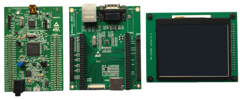
STM32F407 Discovery board, STM32F4DIS-BB base board and STMF4DIS-LCD display module.
For a smooth bring-up session, you need the following hardware components:
★STM32F407 Discovery board from STMicroelectronics (STM32F407G-DISC1)
★USB cable to connect the board with your PC
★Serial cable to connect the base board with your PC
Make sure that you have got the following software packages:
★Embedded Wizard Studio (Evaluation Edition, Starter Edition or Professional Edition)
★Embedded Wizard STM32 Platform Package
★Embedded Wizard Build Environment for STM32F407 Discovery
TIP
If you want to use the free Evaluation Edition of Embedded Wizard Studio and the STM32 Platform Package, please register on our website and select the target STM32F407 Discovery. Then you can download the above software packages.
All customers who licensed Embedded Wizard can visit our download center to get the above software packages (Starter or Professional Edition).
Installing Tools and Software
★Step 1: Install the latest version of Embedded Wizard Studio.
★Step 2: Install the Embedded Wizard STM32 Platform Package.
★Step 3: Download the STM32 ST-LINK utility and install it. Test the connection from PC to Discovery board and the proper installation of the USB drivers: Connect the Discovery board with your PC via USB (make sure to use the ST-LINK USB connector) and start the previously installed STM32 ST-LINK utility. Select the menu item and verify that the connection could be established successfully. Finally, close the STM32 ST-LINK utility.
★Step 4: Create a common STM32 project directory (e.g. \STM32) somewhere in your local file system (e.g. C:\STM32). Please take care that the entire path does not contain space characters.
★Step 5: Download the latest version (Windows ZIP) of the GCC ARM embedded toolchain and unpack it into the common STM32 directory (e.g. C:\STM32\gcc-arm-none-eabi).
★Step 6: Download the latest version of the STM32CubeF4 embedded software for STM32F4 series and unpack it into the common STM32 directory (e.g. C:\STM32\STM32Cube_FW_F4).
★Step 7: Unpack the provided Embedded Wizard Build Environment for STM32F407 Discovery into the common STM32 directory (e.g. C:\STM32\STM32F407-Discovery).
★Step 8: Take a text editor and open the file devenv.cmd that you will find in the subdirectory \Build of the Build Environment. At the beginning of the file, the following environment variables have to be set to the installation paths of the different software components:
•Toolchain_Path - Absolute path of your installed GCC ARM embedded toolchain (Step 5).
•STM32Cube_Path - Absolute path of your installed STM32CubeF4 software (Step 6). Important: This path must not contain any space characters.
•ST-LINK_Utility_Path - Absolute path of your installed STM32 ST-LINK utility (Step 3).
Exploring the Build Environment
The provided Embedded Wizard Build Environment for STM32F407 Discovery contains everything you need to create, compile, link and flash an Embedded Wizard UI application for the STM32F407 target. After unpacking, you will find the following subdirectories and files:
•\Build - This folder contains the necessary stuff to build your UI application: the make utility and the script file StartBuildEnvironment.bat to start a windows command line to build the application. Don't forget to set the path of your installed software packages into the file devenv.cmd.
•\Examples - This folder contains a set of demo applications. Each example is stored in a separate folder containing the entire Embedded Wizard UI project. Every project contains the necessary profile settings for the STM32F407 target. The following samples are provided:
•\HelloWorld - A very simple project that is useful as starting point and to verify that the entire toolchain, your installation and your board is properly working.
•\ColorFormats - This project demonstrates that every UI application can be generated for different color formats: RGBA8888, RGB888, RGBA4444, RGB565, Index8 and LumA44.
•\ScreenOrientation - This demo shows, that the orientation of the UI application is independent from the physical orientation of the display.
•\DeviceIntegration - This example shows the integration of devices into a UI application and addresses typical questions: How to start a certain action on the target? How to get data from a device?
•\AnimatedList - This demo shows the implementation of some fancy scrollable list widgets to set a time and a day of the week. The speciality of this sample application is the magnification effect of the centered list items and the soft fade-in/fade-out effects.
•\BrickGame - The sample application BrickGame implements a classic "paddle and ball" game. In the game, a couple of brick rows are arranged in the upper part of the screen. A ball travels across the screen, bouncing off the top and side walls of the screen. When a brick is hit, the ball bounces away and the brick is destroyed. The player has a movable paddle to bounce the ball upward, keeping it in play.
•\ClimateCabinet - The ClimateCabinet demo shows the implementation of a control panel for a climatic exposure test cabinet. The user can define a heating time, a nominal temperature and humidity, a dwell time and the final cooling time.
•\WaveformGenerator - This WaveformGenerator demo application combines waveforms with different amplitudes and frequencies. The implementation shows the usage of the class Charts::Graph to paint a list of coordinates.
•\Misc - This folder contains some helper modules for printing debug messages and the memory manager used for the Embedded Wizard UI applications.
•\PlatformPackage - This folder contains the necessary source codes and/or libraries of the STM32 Platform Package: Several Graphics Engines for the different color formats (RGBA8888, RGB888, RGBA4444, RGB565, Index8 and LumA44) and the Runtime Environment (in the subdirectory \RTE).
•\TargetSpecific - This folder contains all configuration files and platform specific source codes. The different ew_bsp_xxx files implement the bridge between the Embedded Wizard UI application and the underlying board support package (STM32 hardware drivers) in order to access the display, the graphics accelerator, the serial interface and the clock.
•\Drivers - This folder contains some touch drivers (XPT2046 and STMPE811) and a set of display drivers (ILI9325, ILI9341, SSD1963 and SSD2119) that can be used as templates for your own hardware. Feel free to use them and to adapt them according your needs.
•\Template - This folder contains ready-to-use projects to compile and link an Embedded Wizard generated UI application. They are used for all provided examples and they can be used to build your own UI applications.
•\GeneratedCode - This folder is used to receive the generated code from an Embedded Wizard UI project. All template projects are building the UI application out of this folder. You can create your own UI project and generate the code into the subdirectory \GeneratedCode without the need to adapt the project.
•\Project - This folder contains the prepared projects for GCC (make), IAR Embedded Workbench and Keil MDK-ARM.
•\Source - This folder contains the main.c file, a configuration file for FreeRTOS and the device driver C/H files used for the DeviceIntegration example.
Creating the UI Examples
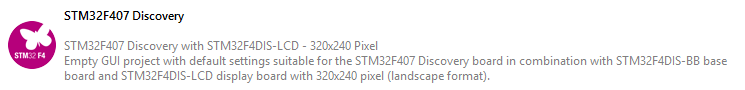
For the first bring up of your system, we recommend to use the example 'HelloWorld':
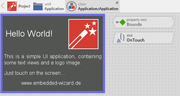
Example 'HelloWorld' within Embedded Wizard Studio.
The following steps are necessary to generate the source code of this sample application:
★Navigate to the directory \Example\HelloWorld.
★Open the project file HelloWorld.ewp with your previously installed Embedded Wizard Studio. The entire project is well documented inline. You can run the UI application within the Prototyper by pressing Ctrl+F5.
★To start the code generator, select the menu items - or simply press F8. Embedded Wizard Studio generates now the sources files of the example project into the directory \Template\GeneratedCode.
Compiling, Linking and Flashing
The following steps are necessary to build and flash the Embedded Wizard UI sample application using the GCC ARM embedded toolchain:
★Navigate to the directory \Build.
★Open StartBuildEnvironment.bat - as a result, a windows command line window should open. In case there are error messages, please edit the file devenv.cmd and set the path variables according your installation paths of the different software packages
★Now start compiling, linking and flashing:
make make install
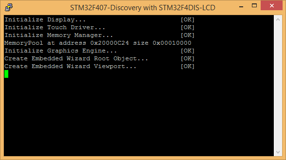
If everything works as expected, the application should be built and flashed to the STM32F407 target.
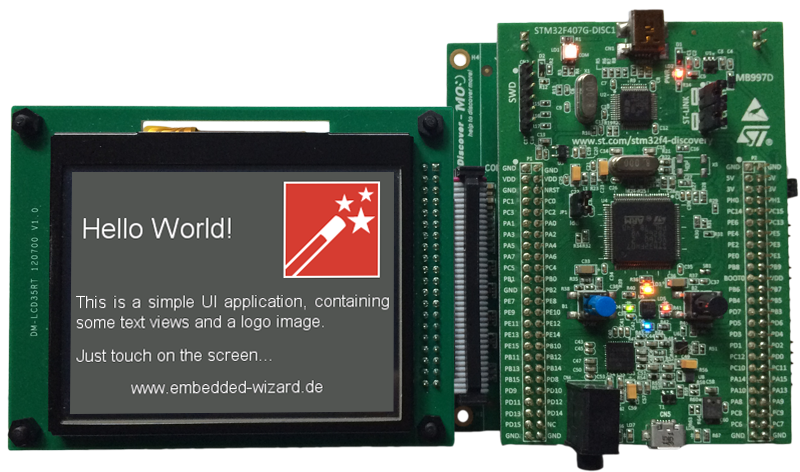
Example 'HelloWorld' running on STM32F407 Discovery board.
All other examples can be created in the same way: Just open the desired example with Embedded Wizard Studio, generate code and rebuild the whole application using simply:
make install
Creating your own UI Applications
In order to create your own UI project suitable for the STM32F407 target, you can create a new project and select the STM32F407 Discovery project template:
As a result you get a new Embedded Wizard project, that contains the necessary Profile attributes suitable for the STM32F407 Discovery board:
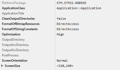
The following profile settings are important for your target:
★The attribute PlatformPackage should refer to an installed STM32 Platform Package. Please note, that for STM32F407 only the color formats RGB565, Index8 or LumA44 can be used.
★The attribute ScreenSize should correspond to the display size of the STM32F407 Discovery board.
★The attributes FormatOfBitmapResources and FormatOfStringConstants should be set to DirectAccess. This ensures that resources are taken directly from flash memory.
★The attribute OutputDirectory should refer to the \Template\GeneratedCode directory within your Build Environment. By using this template, it will be very easy to build the UI project for your target.
★The attribute CleanOutputDirectories should be set to true to ensure that unused source code within the output directory \Template\GeneratedCode will be deleted.
★The attribute PostProcess should refer to \Template\Project\EWARM\EWARM_ew_post_process.cmd if you are working with IAR Embedded Workbench or to \Template\Project\MDK-ARM\MDK-ARM_ew_post_process.cmd if you are working with Keil MDK-ARM.
Now you can use the template project in the same manner as it was used for the provided examples to compile, link and flash the binary.
After generating code, please follow these steps, in order to build your own UI application:
★Start the batch file 'StartBuildEnvironment.bat'. Again, a windows command line window should open.
★Start compiling, linking and flashing:
make install
Most of the project settings are taken directly out of the generated code, like the color format or the screen orientation. Only a few additional settings can be configured directly within the Makefile, like the usage of QSPI flash memory or the usage of the FreeRTOS operating system.
Console output
In order to receive error messages or to display simple debug or trace messages from your Embedded Wizard UI application, a serial terminal like 'Putty' or 'TeraTerm' should be used.
★Connect your STM32F4DIS-BB base board with the PC via serial connection. Open the device manager to get the number of the installed COM port.
★Now you can open your terminal application and connect it via COMx with the following settings: 115200-8-N-1
This terminal connection can be used for all trace statements from your Embedded Wizard UI applications or for all debug messages from your C code.
Working with your own display
If you want to connect your STM32F407 Discovery board with your own display hardware, a couple of modifications might be necessary. Here are a few hints, that might be helpful to manage that migration:
★Within the subdirectory \TargetSpecific\Drivers you will find a set of different display drivers, supporting ILI9325, ILI9341, SSD1963 and SSD2119 via 16-bit 8080 FSMC. You can either re-use one of them to drive your display hardware, or you can use them as template for your own driver development.
★Adapt the file \TargetSpecific\ew_bsp_display.c to access the desired display driver.
★Edit the makefile to use the desired display driver.
★Within the subdirectory \TargetSpecific\Drivers you will find two different touch drivers, supporting XPT2046 via SPI and STMPE811 via I2C. You can either re-use one of them to drive your touch hardware, or you can use them as template for your own driver development.
★Adapt the file \TargetSpecific\ew_bsp_touch.c to access the desired touch driver.
★Edit the makefile to use the desired touch driver.
★If your display hardware provides a different screen size than 320x240 pixel, please ensure to adapt the ScreenSize within your Profile and to adapt the framebuffer defines within the main.c.
Using IAR Embedded Workbench
If you want to use the IAR Embedded Workbench instead of the GCC ARM embedded toolchain, please follow these instructions:
The subdirectory \Template\Project\EWARM contains a template project that is commonly used for all provided Embedded Wizard examples. All Embedded Wizard examples will store the generated code within the common /Template/GeneratedCode folder.
The generated code of an Embedded Wizard example is imported automatically to the IAR Embedded Workbench project using the Project Connection mechanism.
To establish this automatic project import a post process has to be added to the Profile settings within Embedded Wizard Studio:
★Open the desired Embedded Wizard example project.
★Select the profile and set EWARM_ew_post_process.cmd as post process at the Inspector view. You will find the file within the subdirectory \Template\Project\EWARM.
After the Embedded Wizard code generation the installed post process will generate a ewfiles.ipcf file, that controls the import to the IAR Embedded Workbench project.
After returning to IAR Embedded Workbench, the latest generated code and the suitable Embedded Wizard Platform Package will be imported to the IAR Embedded Workbench project (depending on the color format and the screen orientation selected in the Embedded Wizard Profile).
If the color format or the screen orientation was changed, please do a complete rebuild of the IAR Embedded Workbench project.
Using Keil MDK-ARM
If you want to use the Keil MDK-ARM toolchain instead of the GCC ARM embedded toolchain, please follow these instructions:
The subdirectory \Template\Project\MDK-ARM contains a template project that is commonly used for all provided Embedded Wizard examples. All Embedded Wizard examples will store the generated code within the common /Template/GeneratedCode folder.
The generated code of an Embedded Wizard example is imported automatically to the Keil MDK-ARM project using the CMSIS PACK mechanism.
The following steps are needed to establish this automatic project import:
★Install Tara.Embedded_Wizard_Launcher.x.x.x.pack by double clicking. You will find the file within the subdirectory \Template\Project\MDK-ARM.
★Open the desired Embedded Wizard example project.
★Select the profile and set MDK-ARM_ew_post_process.cmd as post process at the Inspector view. You will find the file within the subdirectory \Template\Project\MDK-ARM.
After the Embedded Wizard code generation the installed post process will generate a ewfiles.gpdsc file, that controls the Keil MDK-ARM project import.
In Keil MDK-ARM a dialog appears: "For the current project new generated code is available for import". After confirmation, the latest generated code and the suitable Embedded Wizard Platform Package will be imported to the Keil MDK-ARM project (depending on the color format and the screen orientation selected in the Embedded Wizard Profile).
If the color format or the screen orientation was changed, please do a complete rebuild of the Keil MDK-ARM project.