Using Views: Arc Path Data
The Mosaic framework provides the views Filled Path and Stroked Path intended to display vector graphic shapes (polygons, curves, diagrams, etc.) from provided path data. Depending on the respective view, the shape appears filled (Filled Path view) or as lines drawn along its path edges (Stroked Path view). In order to display a shape, the views require the path information describing the shape precisely.
In its simplest form, a path is composed of line segments, Bézier curves and elliptical arcs. The path can be opened (e.g. a curve within a diagram) or it can be closed (e.g. to describe a circle). In more sophisticated application cases you can compose several sub-paths to one complex path. For example, with two sub-paths, every describing a circle, you can create easily a ring. To construct and store a path (in particular with elliptical shape) you can use the so-called Arc Path Data object.
The following sections are intended to provide you an introduction and useful tips of how to deal with the Arc Path Data object. For the complete reference please see the documentation of the Graphics::ArcPath class. Please note, with Arc Path Data object you only describe the desired shape. Attributes like colors, line thickness, line join style or line caps are determined by properties of the respective view used to fill or stroke the path.
SEE ALSO
Using the Filled Path view to fill a polygon described by a vector graphic path
Using the Stroked Path view to display the outline of a vector graphic path
Please note, the here described Arc Path Data object is a descendant of the more generic Path Data object. While the Arc Path Data object is optimized to simply create arcs, pie segments, circle segments or even ring segments, the generic Path Data object permits you to create any shapes. For this purpose, however, you have to implement code describing the desired shape. With the Arc Path Data object it is sufficient to configure the parameters for the arc by using the properties of the object.
Add new Arc Path Data object
To add a new Arc Path Data object just at the design time of a GUI component do following:
★First ensure that the Templates window is visible.
★In Templates window switch to the folder Resources.
★In the folder locate the template Arc Path Data.
★Drag & Drop the template into the Composer window:
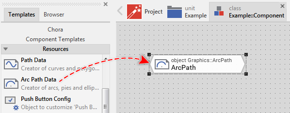
★Eventually name the new added Arc Path Data object.
Inspect the Arc Path Data object
As long as the Arc Path Data object is selected you can inspect and modify its properties conveniently in the Inspector window as demonstrated with the property Radius in the screenshot below:
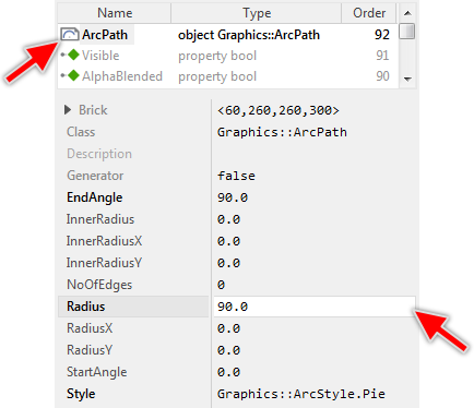
This is in so far worth mentioning as all following sections describe diverse features of the Arc Path data object by explicitly referring to its corresponding properties. If you are not familiar with the concept of a property and the usage of Inspector window, please read first the preceding chapter Compositing component appearance.
Connect the Arc Path Data object to a view
The Arc Path Data object serves as data container where you store the description of a shape. In order to display this shape on the screen you have to connect the Arc Path Data object to one of the both views Filled Path or Stroked Path. Accordingly, the view will display a filled shape (Filled Path view) or it will draw lines along the path edges (Stroked Path view).
To connect an Arc Path Data object to a view you have to assign this object to the property Path of the affected Filled Path or Stroked Path view. With the Inspector Assistant you can conveniently select the right object when you edit the initialization expression for the property Path. For example:
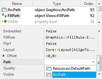
As soon as you have connected the both, the information provided in the Arc Path Data object appears within the view. If desired, you can assign the same Arc Path Data object to several views. If during the runtime of the application, the content of the Arc Path Data object changes, all associated views are updated automatically.
CAUTION
If after assigning the Arc Path Data object to a view, the view displays the shape clipped, you will need to resize the view and adjust its property Offset. With the property Offset you determine the position within the view where to map the origin of the path own coordinate system. In case of the Arc Path Data this corresponds to the center of the constructed arc or ellipse.
Determine the desired arc style
The Arc Path Data object implements internally six different algorithms how to construct the arcs and elliptical shapes. You select the desired algorithm by using its property Style. The following table provides an overview about the available styles:
Style |
Description |
Example |
|---|---|---|
Arc |
Simple elliptical arc. The both arc ends remain opened unless the angle of the arc is equal to or greater than 360.0 degree. |
|
Segment |
Segment of an ellipse with the start and the end positions of the arc being connected together by a straight line segment. If the arc forms a closed ellipse (the angle of the arc is equal to or greater than 360.0 degree), no line segment is added. |
|
Pie |
Shape typical for displaying pie charts. Here the start and the end positions of the outer arc are connected with inner arc (or with the center of the ellipse) by additional straight line segments. If the arc forms a closed ellipse (the angle of the arc is equal to or greater than 360.0 degree), no line segments are added as connections. |
|
PieRounded |
Shape typical for displaying circular bar diagrams with rounded start and end edges. Here the start and the end positions of the outer arc are connected with the inner arc (or with the center of the ellipse) by additional semi-circles. If the arc forms a closed ellipse (the angle of the arc is equal to or greater than 360.0 degree), no semi-circles are added. |
|
PieRoundedStart |
Shape typical for displaying circular bar diagrams with rounded start edges. Here the start position of the outer arc is connected with the inner arc (or with the center of the ellipse) by additional semi-circle. The end position, in turn, is connected by a straight line segment. If the arc forms a closed ellipse (the angle of the arc is equal to or greater than 360.0 degree), no connections are added. |
|
PieRoundedEnd |
Shape typical for displaying circular bar diagrams with rounded end edges. Here the start position of the outer arc is connected with the inner arc (or with the center of the ellipse) by additional straight line segment. The end position, in turn, is connected by a semi-circle. If the arc forms a closed ellipse (the angle of the arc is equal to or greater than 360.0 degree), no connections are added. |
|
Determine the start and the end arc angles
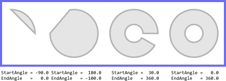
With the both properties StartAngle and EndAngle you determine the desired angles for the start and the end positions of the arc. The properties expect the values being expressed in degree clockwise relative to the positive X-axis. If the absolute value of the difference between the start and the end angles is equal to or greater than 360.0, the arc is considered as a closed ellipse. The following figure demonstrates the effect of the both properties:
TIP
Please note, if EndAngle is greater than the StartAngle the arc is constructed in clockwise direction relative to StartAngle. If EndAngle is less than the StartAngle the arc is constructed in the opposite direction again relative to StartAngle. If both properties are equal, no shape is constructed. In other words, the screen remains empty.
Determine the outer and inner arc radiuses
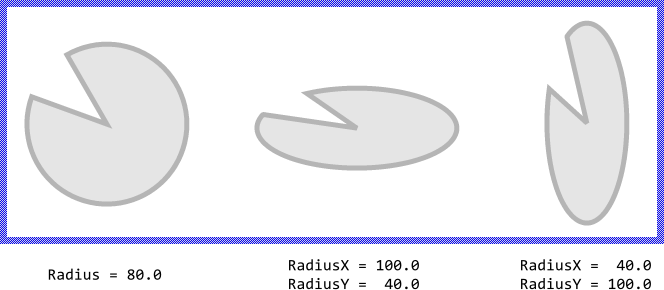
The radius of a circular arc is configured by using the property Radius. More precisely, if you use the both properties RadiusX and RadiusY you can specify different radiuses for the horizontal and vertical dimension of an elliptical arc. The following figure demonstrates the effect of these properties:
If you have configured the Arc Path Data object in its property Style to describe a Pie, PieRounded, PieRoundedStart or PieRoundedEnd you can additionally specify the radius for the inner arc of such shape. You use for this purpose the property InnerRadius. With the related properties InnerRadiusX and InnerRadiusY you can specify individual radiuses for the horizontal and vertical dimension of the inner arc. The following figure demonstrates the effect of these properties:

TIP
Please note, if InnerRadius is equal to or greater than the Radius itself, no shape is constructed. In other words, the screen remains empty. Similarly, if you specify a value for the horizontal or vertical radius leaving the other value initialized with 0.0, no shape appears.
Limit the number of path edges
Per default, the Arc Path Data object estimates by itself how many edges are necessary to optimally construct the arc resulting from the values you specify in the above explained properties. As edges are meant straight line segments the path uses internally to store the shape information. The more edges used to construct an arc, the more precise the resulting shape.
If desired, you can override this automatism and explicitly specify the number of edges to be used. For this purpose modify the property NoOfEdges. Initializing this property with the value 0 (zero) restores the default behavior of the Arc Path Data object to automatically estimate the number of edges. The following figure demonstrates which effect has the modification of the NoOfEdges property. As you see, this property is useful when you intend to construct sophisticated polygons, like a screw head, etc.:


